1
$\begingroup$

I've got a script (Python) that chops 44.1 kHz realtime audio into 10 ms chunks, processes each chunk, and stitches the chunks back together with no added artifacts. I'm trying to create a low-pass filter that operates on each chunk, but every filter I've tried introduces unwanted artifacts.

I've tried creating various types filters, including IIR (Butterworth) and FIR (Hann, Hamming, rectangular windows, etc.), and Remez. The attempted methods of applying the filters to the input signal include just a straight transfer function, convolution, and a forward-then-backward filter (namely scipy.signal.filtfilt). I've also tried the moving average approach, but I don't know what to do near the endpoints of the chunk.

Is there such a filter that is designed for this kind of application?

INPUT WAVE (lots of harmonic content)

|<-- 1 CHUNK  -->|
:                :                :                :
:                :                :                :
: -----       ---:-       -----   :   -----       -:
:|     |     |   : |     |     |  :  |     |     | :
:|     |     |   : |     |     |  :  |     |     | :
:|     |     |   : |     |     |  :  |     |     | :
:       -----    :  -----       --:--       -----  :
:                :                :                :
        V                V                 V
        V                V                 V
     FILTER            FILTER            FILTER
        V                V                 V
        V                V                 V
:                :                :                :
:   ---         -:-         ---   :     ---        :
:  /   \       / : \       /   \  :    /   \       :
: /     \     /  :  \     /     \ :   /     \     /:
:/       \   /   :   \   /       \:  /       \   / :
:         ---    :    ---         :--         ---  :
:                :                :                :

OUTPUT WAVE (less harmonic content)

EDIT: Following the answer from @hotpaw2, I wish to try the IIR approach first (I'm a novice at this, but my gut tells me try IIR first). For discussion purposes, let's define these arrays:

B = transfer function numerator coefficients
A = transfer function denominator coefficients
I0 = previous input array (same size)
I1 = current input array (441 samples)
R0 = previous output, post-filtered (DO WE NEED?)
R1 = current output, desired post-filtered result array

Do I generate the initial conditions from I0 only, or do I need to figure R0 into the equation? To ask another way, here's the Python code I'm trying:

initCon = scipy.signal.filtic(B, A, I0)

Once I have this set of initial conditions, are they directly applied to the filter, or is there more that I need to do with them? Again, the Python code:

R1, _ = scipy.signal.lfilter(B, A, I1, z = initCon)

As the code stands now, it executes but there is a lot of off-frequency buzzing.

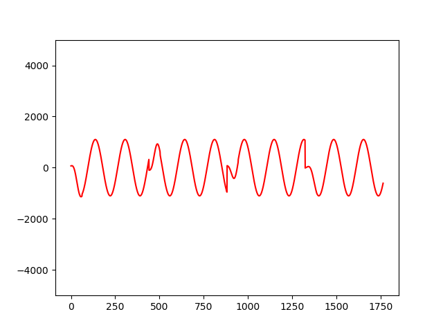
EDIT 2: Just thought I'd post the output of the filter with a sine wave input. It's quite obvious something goes wrong every 441 samples (the beginning of each chunk): Distorted Sine Wave
$\endgroup$
2
  • 1
    $\begingroup$ for a fir filter google overlap and save. for iir filters look at a reference implementation from a library. you essentially need to add the trailing edge from the last block and superimpose it on the current flilteted block $\endgroup$
    – user28715
    Commented Sep 13, 2019 at 23:08
  • 1
    $\begingroup$ All you need is proper initial conditions for each block... $\endgroup$
    – Fat32
    Commented Sep 14, 2019 at 0:42

3 Answers 3

4
$\begingroup$

Filtering a data block usually results in more data than fits in the size of the block. If you throw away this added data, that will produce artifacts across blocks.

For FIR filters, you need to pad each chunk or block with at least the length of the impulse response of your filter before filtering (>= N+M-1). Then use overlap-add or overlap-save (FFT fast convolution algorithms) to process all the extra results from convolution of the added padding (usually carry them over to the next chunk or chunks). Otherwise you are either getting circular convolution artifacts in each block, or are throwing away part of the filter response from applying your filter to each block.

For IIR filters, you need to carry over the filters internal state between chunks, and not start over from zero or other default initial state of the IIR. That state still carries energy from the filter result, and if you throw it away, you will get glitches between chunks.

$\endgroup$
3
  • 1
    $\begingroup$ What is the Internal State? Is this the input to the previous block or the filtered result of the previous block (or both combined somehow)? See also the edit to my original post. $\endgroup$
    – mrhip
    Commented Sep 14, 2019 at 17:40
  • $\begingroup$ I quote the @jeb.jr comment, I will find very useful an answer to his question $\endgroup$ Commented Feb 28, 2021 at 14:39
  • 1
    $\begingroup$ Internal state could be bits of data stored inside the filter algorithm or code, and changing as they are used for computing the output. Sometime those bits of data are visible in the filter output, but sometimes not, depending on the implementation (as in vDSP biquads), and have to be saved and restored separately. Instance variables in reused class objects might be another example. $\endgroup$
    – hotpaw2
    Commented Feb 28, 2021 at 17:48
1
$\begingroup$

This post solved my problem: https://stackoverflow.com/questions/58014131/implementing-blockwise-low-pass-iir-filter-in-python

In the post, Warren Weckesser directed me to his own paper on the topic, where I read that an SOS filter is the solution I need, if I'm going to use an IIR filter. The same paper had a sample of Python code which helped me understand how to handle the initial conditions properly.

$\endgroup$
0
$\begingroup$

This works, but I'm not sure why! The initial conditions are the result of multiplying Z (I don't understand Z's purpose, and why lfiltic() didn't work at all) with the last couple of values from the previous result. Note those last two elements are in reverse order, which maybe says something.

Bparam, Aparam = signal.iirfilter(2, 0.020, btype = 'lowpass', analog =
       False, ftype = 'butter')       # 2nd order Butterworth coefficients

Z = signal.lfilter_zi(Bparam, Aparam) # Part of the init conditions calc

IC = Z * (prevSignal[::-1])[0:2]      # Reverse prevSignal and then grab
                                      #   only the last two elements

filteredSignal, _ = signal.lfilter(Bparam, Aparam, inputSignal, zi = IC)
                                      # Result is continuous and clear

prevSignal = filteredSignal           # Save for the next pass

However, This only works for the 2nd order lowpass filter. If I change the order (e.g. 4th order), the artifacts reappear conspicuously. Is there perhaps a more general form of this that actually works with higher orders of filters?

$\endgroup$
1
  • $\begingroup$ This code isn't set up correctly. See the Accepted Answer. $\endgroup$
    – mrhip
    Commented Sep 23, 2019 at 12:42

Your Answer

By clicking “Post Your Answer”, you agree to our terms of service and acknowledge you have read our privacy policy.

Not the answer you're looking for? Browse other questions tagged or ask your own question.