By allowing an increase in the delay introduced by a digital oversampling filter, the other characteristics of the filter, pass band and stop band ripple and transition band width, can be improved to be arbitrarily close to zero. The oversampling factor can be increased to widen the stop band and to relax requirements on analog filtering, resulting in an increased computational complexity but no significant increase in the delay time introduced by the filter.
Audio DAC's typically have a digital oversampling filter selectable between a low time-delay (latency) filter and a sharp frequency response roll-off filter. The low-delay filter may be a minimum-phase filter or a psychoacoustically tuned compromise between low dispersion (some frequencies being delayed more than others) and low effective delay. The sharp roll-off filter is typically a linear-phase filter with a symmetrical impulse response and a specified maximum ripple in the pass band and in the stop band. This kind of a specification is easy to express in a datasheet and to incorporate in a system design. Comparable equiripple linear-phase filters can be designed in Octave using remez, here with equal weight of pass band and stop band ripple:
pkg load signal
x2x = []; x4x = [];
for n = [16:86]
  b2x = remez(2*n, [0, 20/44.1, (44.1-20)/44.1, 1], [1, 1, 0, 0], [1, 1], "bandpass", 128);
  b4x = remez(2*n, [0, 20/(44.1*2), (44.1-20)/(44.1*2), 1], [1, 1, 0, 0], [1, 1], "bandpass", 128);
  [h2x, w2x] = freqz(b2x); [h4x, w4x] = freqz(b4x);
  x2x = [x2x; (length(b2x)-1)/2/2, 20*log10(abs(h2x(end)))];
  x4x = [x4x; (length(b4x)-1)/2/4, 20*log10(abs(h4x(end)))];
endfor
plot(x2x(:,1), x2x(:,2), "x", x4x(:,1), x4x(:,2), "x", 29.2, -100, "x", 39.5, -110, "x", 43.3828125, -110, "x")
xlabel("group delay / f_s");
ylabel("stop band ripple (dB)");
text(29.2-2, -100-4, "AK4499");
text(39.5-2, -110+4, "CS43198");
text(43.3828125-2, -110-4, "AD1955");
grid on
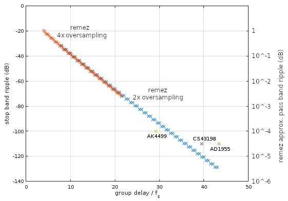
The script designs various order filters (limited by what remez can handle without numerical problems) for a pass band from 0 to 20 kHz and a stop band starting at 24.1 kHz, to be operated at a small selection of oversampling sampling frequencies of 2 and 4 times the 44.1 kHz sampling frequency, and plots (Fig. 1) the stop band ripple characteristics together with those of equivalent oversampling digital filters of flagship audio DAC's from Asahi Kasei (AK4499), Analog Devices (AD1955), and Cirrus Logic (CS43198).

Figure 1. Stop band and pass band ripple for 2x (blue) and 4x (orange) oversampling remez-designed linear-phase low-pass digital filters with equal pass and stop band weights, as function of impulse response half-length in units of the sampling period at the 1x sampling frequency of 44.1 kHz. Also plotted are stop band ripple performance figures for a selection of DAC oversampling filters with the corresponding pass band ripple being specified as 5×10^-3 dB for the 8x oversampling digital filter of AK4499, 10^-2 dB for the combined digital and analog filter of CS43198, and 2×10^-4 dB for the 8x oversampling digital filter of AD1955. All filters compared here have identical transition band boundaries: 20 kHz to 24.1 kHz.
For 44.1 kHz sampling frequency, Fig. 1 gives a lower bound on linear-phase oversampling digital filter performance as function of delay introduced by the filter, when pass band and stop band ripple are equally weighted. This bound does not depend significantly on the oversampling ratio. DAC manufacturers may choose a different weighting for example to gain lower stop band ripple by increasing the pass band ripple, as in the case of AK4499. They may also optimize the filters by other criteria than strict equiripple. For example, the filter may include compensation for attenuation of high frequencies by the analog circuitry (zero-order hold, RC-filters, etc.), and the filter delay characteristics may suffer from using a computationally efficient multi-rate implementation.
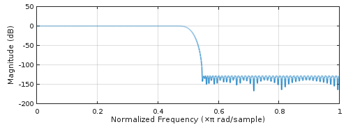
We can have a closer look at the highest-performance filter in Fig. 1 which comes from remez(2*86, [0, 20/44.1, (44.1-20)/44.1, 1], [1, 1, 0, 0], [1, 1], "bandpass", 128), by plotting its impulse response (Fig. 2) and frequency response using freqz (Fig. 3):

Figure 2. Impulse response of the highest-performance linear-phase 2x oversampling filter from remez.

Figure 3. Frequency response of the highest-performance linear-phase 2x oversampling filter from remez.
It would be more interesting to look at 8x oversampling filters, but remez fails with error: remez: insufficient extremals--cannot continue.


