This can be accomplished by changing the carrier frequency using a Numerically Controlled Oscillator (NCO) which maintains an accurate and continuous phase versus time trajectory via the phase accumulator. This is markedly different than changing the frequency with a classical PLL where we would typically break and reacquire lock to change frequency resulting in a random starting phase position at each carrier. Since the desired phase location is repeatably known at each symbol starting position, we can measure phase error to correct for carrier offset.
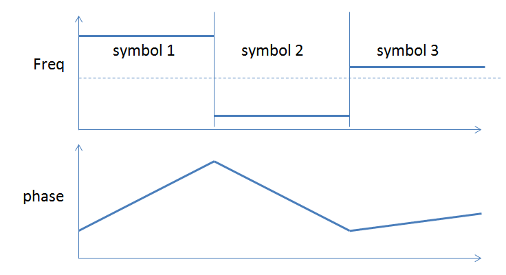
This is further demonstrated with the following graphics:
A typical non-hopped coherent receiver with a carrier offset would have a phase error versus time such as that shown in the plot below (where the specific modulation is not shown).

Since the question is not how to do carrier tracking in general, I assume for purposes of this post that approaches to recover and track the carrier in this circumstance are well understood.
Now consider a frequency hopped system, where we have used an NCO to change the carrier frequency. Without a carrier offset (the signal as observed at the transmitter), the phase versus time for three successive symbols, with each at a new carrier frequency, would appear as follows (again with the specific modulation used not shown). Frequency is the derivative of phase, so a constant frequency offset result in a linear slope of phase, as shown.

With the same carrier offset as we first presented, the phase trajectory would actually be as follows in the receiver:

Even though we are changing frequency, because the phase is continuous and predictable (no random phase inserted at the start of each symbol as in the PLL switched case), we are still able to determine the background phase slope (error) that is used to drive the carrier tracking loop.
For more details on NCO see: Numerically Controlled Oscillator (NCO) for phasor implementation?
For more details on Carrier Tracking see:
High modulation index PSK - carrier recovery


