I am currently studying two Butterworth and Chebyshev low-pass filters of order $n =3$ and $n=2$ respectively, whcih are in fact two prototypes to make a bandpass filter. The transfer function that I have is the following one: $$H(j\omega) = 2\sqrt{\frac{R_G}{R_L}}\frac{1}{R_G(C+\frac{D}{R_L}) + A + \frac{B}{R_L}}$$ where $R_G$ is the impedance in series with the generator and $R_L$ is the load impedance
For the Butterworth filter the data is the following: $$\begin{align}R_G&=R_L=50\;\Omega\\ A &=1 -0.708\omega^2\\ B &=j59\omega \\ C &=j(0.024\omega -0.008496\omega^3)\\ D &= 1-0.708\omega^2\end{align}$$
and for the Chebyshev filter the data is the following:
$$\begin{align}R_G&=50\Omega\quad R_L=18.8\;\Omega\\
A &=1\\
B &=j34.25\omega \\
C &=j0.036\omega\\
D &=1-1.233\omega^2\end{align}$$
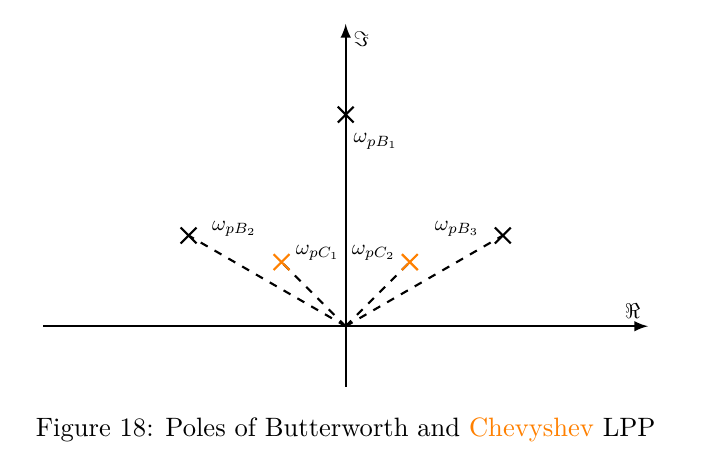
and this is the poles diagram computed with the data above of such circuits:

where: $$\begin{align} \omega_{pB_1} &= j1.66\\ \omega_{pB_2} &= -1.45+j0.83\\ \omega_{pB_3} &= 1.45+j0.83\\ \omega_{pC_1} &= -0.9 + j0.55\\ \omega_{pC_2} &= 0.9 + j0.55 \end{align}$$
It is clear that both systems are going to be unstable since they have poles in the right-half plane, but how will these poles look in the time domain? I have read articles like this one or this one and some questions on this website, and I know that if they were complex conjugated poles the response in time domain would be a sinusoid type signal.
I am asking this because the majority of the examples have two conjugated poles, which in this case they are not, and hence the time domain expressions won't be sinusoids, or I am wrong? Could someone answer with the inverse Laplace transform in Matlab of my transfer function?
Note that I am not asking for my job to be done, I have already made it, but some more information about those poles will be appreciated.
Thank you.
