-1
$\begingroup$

I need help with demodulating DSB-SC signals. I took the appproach of using the FFT as follows: I have a signal. I FFT it. Then i take real and imaginary part of the FFT and translate some values:

real[i] = real[i + xx]
imag[i] = imag[i + xx]

then i reconstruct the signal by IFFT. The result is that a demodulation in the signal, very precise in frequency. But the problem is that there are some glitches due to spectral leakage.

According to your experience, is this a good approach for demodulating DSB-SC or is there a better approach?

Thanks a lot in advance

$\endgroup$
11
  • $\begingroup$ You'll probably get a better answer if you can provide more detail. How do those glitches manifest themselves? Why do you think they're due to spectral leakage? $\endgroup$
    – MBaz
    Commented Jun 27, 2017 at 14:36
  • $\begingroup$ I don't have any other explanation... $\endgroup$
    – P.Martin
    Commented Jun 27, 2017 at 14:56
  • $\begingroup$ They manifest themselves in amplitude hops in the modified signal $\endgroup$
    – P.Martin
    Commented Jun 27, 2017 at 14:56
  • $\begingroup$ How can i send an image of the glitch? $\endgroup$
    – P.Martin
    Commented Jun 27, 2017 at 15:01
  • $\begingroup$ What i'm trying to do is to demodulate a DSB-SC signal... $\endgroup$
    – P.Martin
    Commented Jun 27, 2017 at 16:15

2 Answers 2

2
$\begingroup$

Based on the comments from the OP the real question is "How to demodulate a DSB-SC signal." and I edited the title and intro in the question to make that consistent with the comment...please reject edits if that is incorrect).

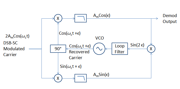
I don't believe that the FFT is an efficient approach for this. A straight forward approach to demodulate a DSB-SC signal for comparison is to simply multiply the signal with the recovered carrier. Carrier recovery can be done by simply squaring the signal, which will create a dominant tone at twice the carrier frequency which can then be divided by two. Another approach is the Costas Loop as shown in the diagram below which will eliminate any phase offsets between the recovered carrier and the signal automatically due to the loop. The loop will lock such that $cos(\epsilon) = 1$ recovering the modulation signal $A_m$. Both approaches can be completely implemented digitally with significantly less resources than an FFT/IFFT.

Costas Loop

$\endgroup$
9
  • $\begingroup$ ok, how can i implement the LPF? $\endgroup$
    – P.Martin
    Commented Jun 28, 2017 at 7:18
  • $\begingroup$ @P.Martin The LPF is a digital FIR filter. The LPF as well as multiplier, VCO, quadrature splitter would all be implemented digitally as a "Digital DownConverter". This consists of an Numerically Controlled Oscillator (NCO) that generates Sine and Cosine outputs at your carrier rate, digital multipliers as shown in the figure, and the FIR low pass filters. The loop filter is also implemented digitally, usually in this form as an accumulator added to a proportional gain path (for a PI loop). $\endgroup$ Commented Jun 28, 2017 at 11:25
  • $\begingroup$ @P.Martin But to start if you are dealing with you signal in the simulation world where you know that you can generate a phase coherent copy of your carrier- then just multiply your signal by your carrier and low pass filter the output of the multiplier. This will give you a sense as to how the demodulation works (and you can likewise do the math and see what is occuring). In practical applications it is recreating the carrier and tracking that (carrier recovery) that leads to further complication in the implementation as shown. $\endgroup$ Commented Jun 28, 2017 at 11:28
  • $\begingroup$ @P.Martin A carrier recovery by squaring your signal (multiply the DSB-SC signal with itself) and then dividing in frequency by two may be simplest for you if you don't understand well the Costas Loop approach shown. Typically with the squaring approach the carrier will be noisier and requires filtering (often with a PLL). Hard-limiting your DSB-SC prior to squaring may help (just for the carrier recovery, not in your signal demodulation). $\endgroup$ Commented Jun 28, 2017 at 11:31
  • $\begingroup$ Dan, i have implemented the Costas Loop with double buffering architecture, but i have amplitude difference of the recovered signal (the output of every processed buffer is very good). I have implemented the VCO by adding component by component the output of the loop product $\endgroup$
    – P.Martin
    Commented Jul 14, 2017 at 17:46
1
$\begingroup$

You may like to read "A simple low-cost linear demodulator for DSB-SC".

As you will find out, it is much easier to implement it than the well-known Costas Loop or Squaring Loop.

If you have good knowledge in electronics, as it seems you have, you can implement rather easily each function-box of this simple DSB-SC demodulator (I used it already for my private short range RF links in the 80's when I had no phone line at home).

Kerim

$\endgroup$
5
  • $\begingroup$ Hi Kerim! Yes this is a common technique (carrier recovery by squaring and dividing by two), but then most often done by multiplying the recovered carrier with a signal instead of passing it with a switch; although either will work I believe you will find that the multiplier will give a 3 dB SNR advantage which is why you would see that more predominantly used. The multiplier is essentially a switch that either passes the signal or passes the signal with 180 degree phase shift. $\endgroup$ Commented Dec 14, 2017 at 11:25
  • $\begingroup$ You are right, Dan. But at that time, early 80's, I had to use whatever was available to me as ICs. And since using the chopping method worked fine in my private links I didn't look further. For instance, I did this project as an MS thesis to prove that demodulating a DSB-SC signal is much easier and reliable than demodulating a SSB-SC one. This has to be normal since the former takes twice the bandwidth. But I am afraid that even in our days the undergraduates in communications around the world hear the inverse of this truth. After I built and tested the project circuit in the lab, but... $\endgroup$
    – KerimF
    Commented Dec 17, 2017 at 23:06
  • $\begingroup$ ...but before submitting the project, I had to return home to revive my humble private business (designing various electronic controllers for the local market). I guess you noticed that the trick of the duty-cycle shaper (from 50% to 25% or 75%) gives the possibility to use just one PLL (Fvco=2*Fc) to achieve synchronization. After I downloaded and run LTspice a few years ago (I am 69 now), I had the idea to simulate my work and, as a hobby, I... $\endgroup$
    – KerimF
    Commented Dec 20, 2017 at 0:40
  • $\begingroup$ Very nice Kerim! Yes often simpler (and lower cost) is highly preferred, well done. $\endgroup$ Commented Dec 20, 2017 at 2:53
  • $\begingroup$ (Just to complete my post)... I updated some parts of it to get a faster and cleaner response. Although this idea was great 35 years ago (even a manager at Plessey in UK was interested to know it), its value today is just academic. It just proves that a simple reliable linear demodulator of DSB-SC does exist. So in case you find it interesting, please feel free to use it the way you like as if it is yours. $\endgroup$
    – KerimF
    Commented Dec 20, 2017 at 23:17

Your Answer

By clicking “Post Your Answer”, you agree to our terms of service and acknowledge you have read our privacy policy.

Not the answer you're looking for? Browse other questions tagged or ask your own question.