5
$\begingroup$

I think I must have misunderstood something regarding the relation between impulse and frequency responses.

I have calculated the Impulse Response Function, IRF, from the Frequency Response Function, FRF, by FFT and then I find some strange things, among these that my assumption that the IRF will always be real is not correct. I have in my code used only the real part of the result from FFT when defining the IRF. Then the amplitude response (and phase) are not correct when I convolve my signal with a sine wave. I expect no phase lag and a slight amplification of a sine wave with period 10 seconds, but get a signal with the wrong amplitude and a slight phase mismatch instead.

What should I do with the imaginary part of the IRF i get back from FFT?


Details for those with a lot of time:

I am using Python and NumPy to try to work out the response of a LTI system to an arbitrary response. I guess the same would apply to Matlab or any other numerical tool implementing DFT. I know a priori the frequency response function, FTR (called a Response Amplitude Operator, RAO, in my field, naval hydrodynamics). As a test case I define my FRF as follows:

# Define RAO
omegas = 2*pi / numpy.array([5, 9, 10, 11, 30])
rao = numpy.array([0, 0, 1.1, 0, 0], dtype=complex) # Fake "ship roll" RAO

The frequency response for my fake ship roll RAO is 1.1 for a wave period of 10 seconds and zero when you get more than one second in wave period away from the peak.

I am using numpy.fft to find the impulse response function, IRF. I interpolate my RAO and apply FFT:

def make_double(x):
    """
    Make a double spectrum by copying the input reversed
    Does not divide the results by two after the mirroring 
    """
    return numpy.concatenate((x, x[::-1]))

def rao_to_irf(omegas, rao, tmax, dt):
    """
    Take an RAO defined for a set of (increasing) frequencies and 
    compute the corresponding impulse response function by FFT.

    The RAO is inter-/extrapolated to the necessary delta omega
    required to obtain the wanted time step, delta t

    The RAO is assumed to be a complex array
    """
    assert omegas[0] < omegas[-1], "The RAO frequencies, omegas, must be given in increasing order"

    N = numpy.ceil(tmax/dt)
    dw = pi/N/dt

    omegas_long = numpy.arange(N, dtype=float)*dw
    rao_long = interpolate_complex_1d(omegas, rao, fill=0)(omegas_long)

    irf = ifft(make_double(rao_long))[:N]*N/tmax
    t = numpy.arange(N)*dt

    return t, irf.real

Now I have an IRF (?). To check the response I also implemented the inverse and see that the RAO/FRF calculated from the IRF looks similar to the input RAO (when interpolated to constant frequency spacing).

I can now combine my RAO/FRF with a wave spectrum and perform a time realization using FFT. I also make a realization of the spectrum to get the unmodified input wave signal. This signal I convolve with the IRF.

I get the expected result if my RAO/FRF is 1 for all frequencies (meaning I get the wave signal back). However the response to the peaked RAO defined above is not as I expect. The time realization from the wave spectrum multiplied by the RAO^2 is not the same as the result of the convolution. Should not these match. I am pretty sure our code to make realizations of response spectra works as it should and I have tested with wave spectra consisting of one pure sine wave and the response is as expected with an FFT of the response spectrum, but not when using convolution
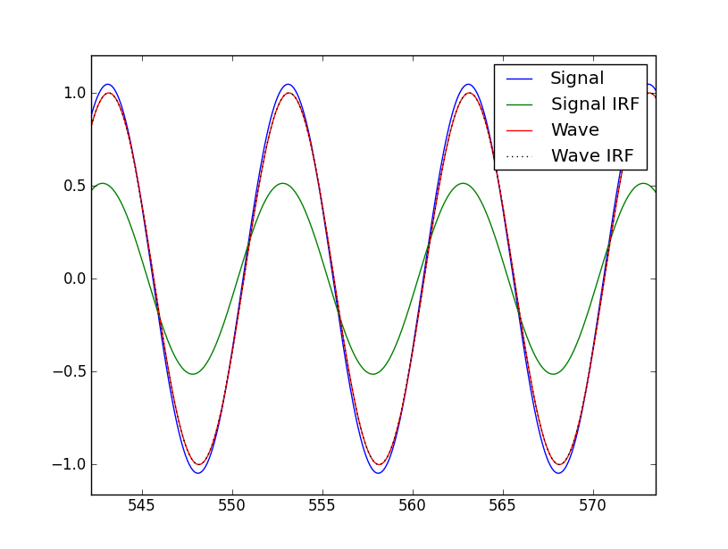
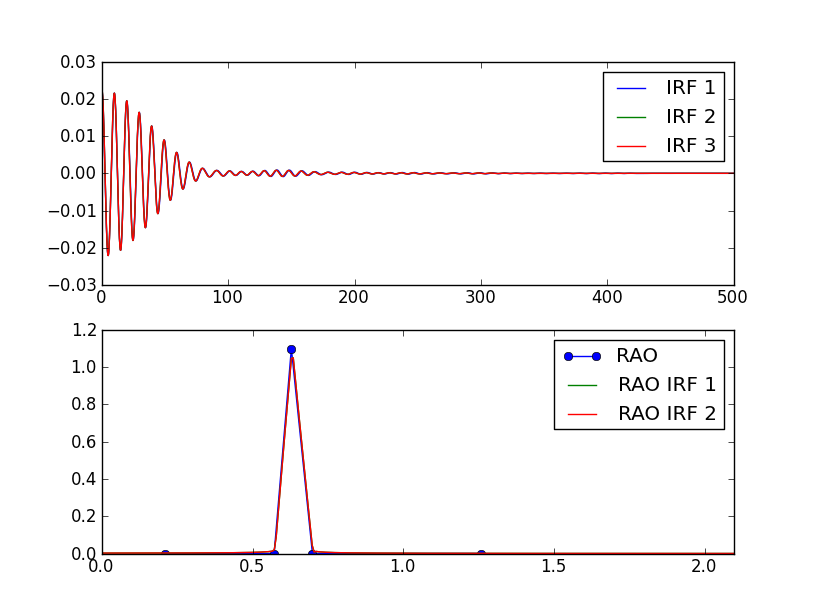
enter image description here

Sorry for the convoluted question

$\endgroup$

2 Answers 2

2
$\begingroup$

Filters are usually real, not complex, but occasionally they are complex. What do you do with the complex impulse response? Convolve it with your data, just like you would with a real impulse response. This will likely result in a complex output. What you do with the imaginary part at that point depends on the situation. Sometimes it makes sense to leave the data complex, sometimes it makes sense to get rid of the imaginary part.

The imaginary part of the filter would particularly affect the output phase, so the fact that the output phase is not what you expected when you only used the real part of the impulse response makes sense.

$\endgroup$
6
  • 6
    $\begingroup$ Convolution with a complex filter is not equivalent to convolving the real and imaginary parts separately. For a complex filter, convolution is specified as an inner product of the filter coefficients (its impulse response) and the input signal. There are cross-terms in that inner product where the real part of the impulse response multiplies the imaginary part of the input signal, and vice versa. If you perform two separate real convolutions, you don't get those terms. $\endgroup$
    – Jason R
    Commented Jun 5, 2012 at 14:15
  • $\begingroup$ @JasonR I saw that that portion of the answer was not very clear, so I decided to get rid of it. $\endgroup$
    – Jim Clay
    Commented Jun 5, 2012 at 14:32
  • $\begingroup$ Hi, this did change the results, but not quite as I had hoped. Can ther be differet reasons why the amplitude is less than what I expect? !new results $\endgroup$
    – Tormod
    Commented Jun 5, 2012 at 14:33
  • $\begingroup$ The dashed lines are the output from convolution with the complex IRF and output = output.real + output.imag $\endgroup$
    – Tormod
    Commented Jun 5, 2012 at 14:36
  • $\begingroup$ @Tormod It would be easier to understand and help if you could explain clearly what Signal, Signal IRF, Wave, Wave IRF, IRF 1/2/3, RAO, and RAO IRF 1/2 are. I don't necessarily need to know what the physical context- just things like what is the input, what is the filter, and what is the output. $\endgroup$
    – Jim Clay
    Commented Jun 5, 2012 at 15:01
2
$\begingroup$

A function with real even symmetry and imaginary odd symmetry will always have a purely real DFT/IDFT. If you define the frequency response for only positive frequencies, then your spectrum does not have any symmetry about 0, and will have a complex impulse response.

This should make sense, because cosine functions are even and sine functions are odd. If you have an arbitrary even function, you would only be able to express it in terms of cosines, not sines. Hence, it's frequency spectrum would be purely real.

An even impulse response would have coefficients for positive and negative times, which means it would have to see into the future. In order to implement this in a real time filter, you would shift the impulse response until it can be implemented with only data that has already happened. This shift will cause a linear phase response in the frequency domain.

If you are using an FFT, keep in mind that negative frequencies will be aliased up to the region below the sample rate frequency.

$\endgroup$

Your Answer

By clicking “Post Your Answer”, you agree to our terms of service and acknowledge you have read our privacy policy.

Not the answer you're looking for? Browse other questions tagged or ask your own question.