added 26 characters in body
Source Link
Dan Boschen
  • 55k
  • 2
  • 59
  • 143

It is not typical to transmit rectangular pulses as it results in a much wider spectrum than is necessary, resulting in poor spectrum efficiency and more susceptibility to group delay distortion across the bandwidth.

Assuming that the wider bandwidth is not a concern here (and I don't actually see that the OP's resulting waveform is distorted to the point where a simple demodulation can't be performed) then squaring the signal for carrier recovery would certainly be doable for the OP's case. The resulting squared signal does have a lot of amplitude variation, but notably will have a much stronger and well defined second harmonic (that would be very clear by evaluating the FFT of the squared output). The job to complete carrier recovery is to filter 2nd harmonic output and then divide the resulting signal by two. A common approach for filtering with such "squaring loops" is to phase lock a clean 2nd harmonic oscillator. This is effectively what becomes a very narrow auto-tuning bandpass filter (where-as a fixed filter would fail if the carrier offset exceeded the fixed bandwidth).

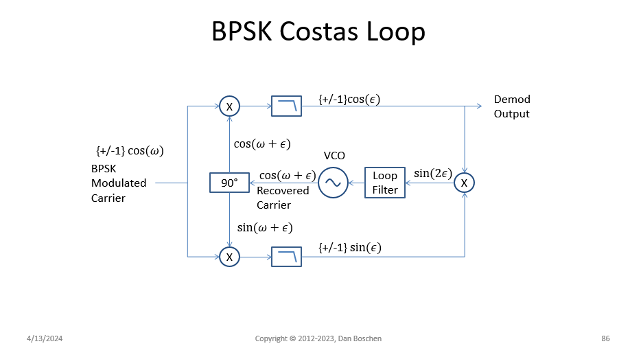
Another approach that is ultimately more compact (and more common) is a "Costas Loop" as shown in the diagram below, which should also work just fine with the OP's waveform as is. This can be implemented in the analog domain with a Voltage Controlled Oscillator (VCO) as shown, or as a direct digital loop using an Numerically Controlled Oscillator (NCO). The low pass filters shown are "matched filters", so in the OP's case with rectangular pulses would be an integration over the symbol duration $T$ (and can be optimized to match that actual pulse shape due to the coupling circuit, but a simple "Integrate and Dump" would be sufficient for initial operation: where the multiplier outputs are summed or accumulated over the duration of one symbol and the final value selected as the "dump" value for each symbol and the accumulators then reset for the next symbol).

BPSK Costas Loop

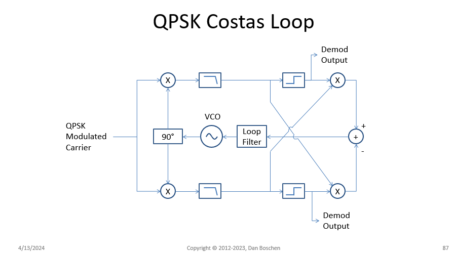
I detail the NCO operation in DSP.SE #37803. Observe how we can extend the Costas Loop to QPSK (and QAM if we change the decision blocks from two-level as shown below for QPSK, to instead be multi-level as needed for QAM):

enter image description here

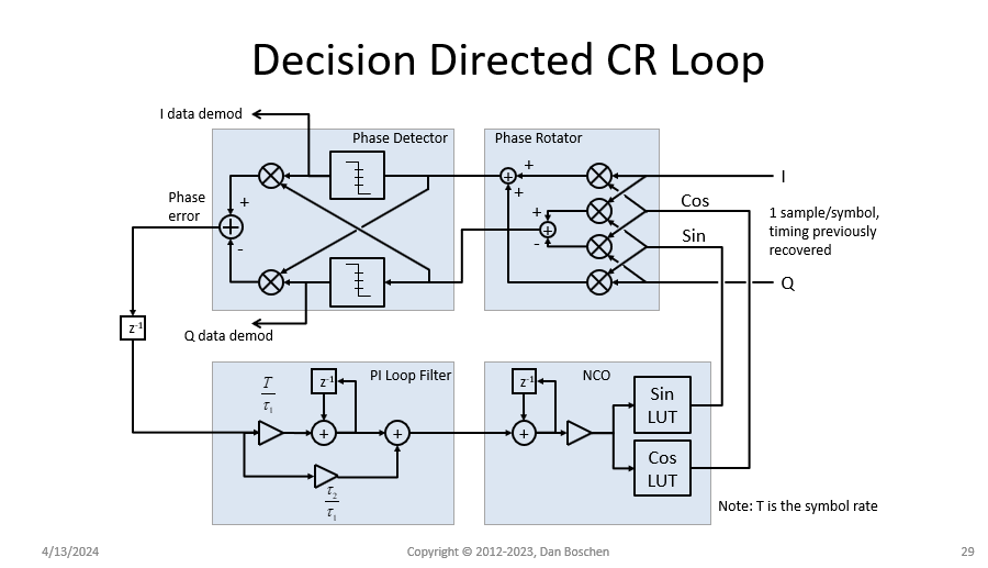
A complete digital implementation for BPSK, QPSK and QAM showing the loop filter as a "PI Loop Filter", and the NCO as a counter with a sine and cosine lookup table (which in a simulation the counter output is scaled be phase as $2\pi n/N$ with $n=0,1, \ldots N-1$, and the lookup tables are a computation of the I and Q outputs as $I+jQ = e^{j\phi}$.)

QAM demodulator

What isn't shown but also important is the job of Timing Recovery. The recovered timing clock is what would be used to reset and dump the accumulators if "integrate and dump" filters are used in the Costas Loop.

Like what you see? These details are part of my online course "DSP for Software Radio" course where I bring practical DSP together with intuition for a deeper and more creative understanding of signal processing concepts. You can find the latest course listings at https://dsprelated.com/courses and https://ieeeboston.org/courses/ . Other DSP courses are starting this month (April 18 and April 25 2024)!

It is not typical to transmit rectangular pulses as it results in a much wider spectrum than is necessary, resulting in poor spectrum efficiency and more susceptibility to group delay distortion across the bandwidth.

Assuming that is not a concern (and I don't actually see that the OP's resulting waveform is distorted to the point where a simple demodulation can't be performed) then squaring the signal for carrier recovery would certainly be doable for the OP's case. The resulting squared signal does have a lot of amplitude variation, but notably will have a much stronger and well defined second harmonic (that would be very clear by evaluating the FFT of the squared output). The job to complete carrier recovery is to filter 2nd harmonic output and then divide the resulting signal by two. A common approach for filtering with such "squaring loops" is to phase lock a clean 2nd harmonic oscillator. This is effectively what becomes a very narrow auto-tuning bandpass filter (where-as a fixed filter would fail if the carrier offset exceeded the fixed bandwidth).

Another approach that is ultimately more compact (and more common) is a "Costas Loop" as shown in the diagram below, which should also work just fine with the OP's waveform as is. This can be implemented in the analog domain with a Voltage Controlled Oscillator (VCO) as shown, or as a direct digital loop using an Numerically Controlled Oscillator (NCO). The low pass filters shown are "matched filters", so in the OP's case with rectangular pulses would be an integration over the symbol duration $T$ (and can be optimized to match that actual pulse shape due to the coupling circuit, but a simple "Integrate and Dump" would be sufficient for initial operation: where the multiplier outputs are summed or accumulated over the duration of one symbol and the final value selected as the "dump" value for each symbol and the accumulators then reset for the next symbol).

BPSK Costas Loop

I detail the NCO operation in DSP.SE #37803. Observe how we can extend the Costas Loop to QPSK (and QAM if we change the decision blocks from two-level as shown below for QPSK, to instead be multi-level as needed for QAM):

enter image description here

A complete digital implementation for BPSK, QPSK and QAM showing the loop filter as a "PI Loop Filter", and the NCO as a counter with a sine and cosine lookup table (which in a simulation the counter output is scaled be phase as $2\pi n/N$ with $n=0,1, \ldots N-1$, and the lookup tables are a computation of the I and Q outputs as $I+jQ = e^{j\phi}$.)

QAM demodulator

What isn't shown but also important is the job of Timing Recovery. The recovered timing clock is what would be used to reset and dump the accumulators if "integrate and dump" filters are used in the Costas Loop.

Like what you see? These details are part of my online course "DSP for Software Radio" course where I bring practical DSP together with intuition for a deeper and more creative understanding of signal processing concepts. You can find the latest course listings at https://dsprelated.com/courses and https://ieeeboston.org/courses/ . Other DSP courses are starting this month (April 18 and April 25 2024)!
It is not typical to transmit rectangular pulses as it results in a much wider spectrum than is necessary, resulting in poor spectrum efficiency and more susceptibility to group delay distortion across the bandwidth.

Assuming that the wider bandwidth is not a concern here (and I don't actually see that the OP's resulting waveform is distorted to the point where a simple demodulation can't be performed) then squaring the signal for carrier recovery would certainly be doable for the OP's case. The resulting squared signal does have a lot of amplitude variation, but notably will have a much stronger and well defined second harmonic (that would be very clear by evaluating the FFT of the squared output). The job to complete carrier recovery is to filter 2nd harmonic output and then divide the resulting signal by two. A common approach for filtering with such "squaring loops" is to phase lock a clean 2nd harmonic oscillator. This is effectively what becomes a very narrow auto-tuning bandpass filter (where-as a fixed filter would fail if the carrier offset exceeded the fixed bandwidth).

Another approach that is ultimately more compact (and more common) is a "Costas Loop" as shown in the diagram below, which should also work just fine with the OP's waveform as is. This can be implemented in the analog domain with a Voltage Controlled Oscillator (VCO) as shown, or as a direct digital loop using an Numerically Controlled Oscillator (NCO). The low pass filters shown are "matched filters", so in the OP's case with rectangular pulses would be an integration over the symbol duration $T$ (and can be optimized to match that actual pulse shape due to the coupling circuit, but a simple "Integrate and Dump" would be sufficient for initial operation: where the multiplier outputs are summed or accumulated over the duration of one symbol and the final value selected as the "dump" value for each symbol and the accumulators then reset for the next symbol).

BPSK Costas Loop

I detail the NCO operation in DSP.SE #37803. Observe how we can extend the Costas Loop to QPSK (and QAM if we change the decision blocks from two-level as shown below for QPSK, to instead be multi-level as needed for QAM):

enter image description here

A complete digital implementation for BPSK, QPSK and QAM showing the loop filter as a "PI Loop Filter", and the NCO as a counter with a sine and cosine lookup table (which in a simulation the counter output is scaled be phase as $2\pi n/N$ with $n=0,1, \ldots N-1$, and the lookup tables are a computation of the I and Q outputs as $I+jQ = e^{j\phi}$.)

QAM demodulator

What isn't shown but also important is the job of Timing Recovery. The recovered timing clock is what would be used to reset and dump the accumulators if "integrate and dump" filters are used in the Costas Loop.

Like what you see? These details are part of my online course "DSP for Software Radio" course where I bring practical DSP together with intuition for a deeper and more creative understanding of signal processing concepts. You can find the latest course listings at https://dsprelated.com/courses and https://ieeeboston.org/courses/ . Other DSP courses are starting this month (April 18 and April 25 2024)!
added 456 characters in body
Source Link
Dan Boschen
  • 55k
  • 2
  • 59
  • 143

It is not typical to transmit rectangular pulses as it results in a much wider spectrum than is necessary, resulting in poor spectrum efficiency and more susceptibility to group delay distortion across the bandwidth.

Assuming that is not an issuea concern (and I don't actually see that the OP's resulting waveform is distorted to the point where a simple demodulation can't be performed) then squaring the signal for carrier recovery would certainly be doable for the OP's case. The resulting squared signal does have a lot of amplitude variation, but notably will have a much stronger and well defined second harmonic (that would be very clear by evaluating the FFT of the squared output). The job to complete carrier recovery is to filter 2nd harmonic output and then divide the resulting signal by two. A common approach for filtering with such "squaring loops" is to phase lock a clean 2nd harmonic oscillator. This is effectively what becomes a very narrow auto-tuning bandpass filter (where-as a fixed filter would fail if the carrier offset exceeded the fixed bandwidth).

Another approach that is ultimately more compact (and more common) is a "Costas Loop" as shown in the diagram below, which should also work just fine with the OP's waveform as is. This can be implemented in the analog domain with a Voltage Controlled Oscillator (VCO) as shown, or as a direct digital loop using an Numerically Controlled Oscillator (NCO). The low pass filters shown are "matched filters", so in the OP's case with rectangular pulses would be an integration over the symbol duration $T$ (and can be optimized to match that actual pulse shape due to the coupling circuit, but a simple "Integrate and Dump" would be sufficient for initial operation: where the multiplier outputs are summed or accumulated over the duration of one symbol and the final value selected as the "dump" value for each symbol and the accumulators then reset for the next symbol).

BPSK Costas Loop

I detail the NCO operation in DSP.SE #37803. Observe how we can extend the Costas Loop to QPSK (and QAM if we change the decision blocks from two-level as shown below for QPSK, to instead be multi-level as needed for QAM):

enter image description here

A complete digital implementation for BPSK, QPSK and QAM showing the loop filter as a "PI Loop Filter", and the NCO as a counter with a sine and cosine lookup table (which in a simulation the counter output is scaled be phase as $2\pi n/N$ with $n=0,1, \ldots N-1$, and the lookup tables are a computation of the I and Q outputs as $I+jQ = e^{j\phi}$.)

QAM demodulator

What isn't shown but also important is the job of Timing Recovery. The recovered timing clock is what would be used to reset and dump the accumulators if "integrate and dump" filters are used in the Costas Loop.

Like what you see? These details are part of my online course "DSP for Software Radio" course where I bring practical DSP together with intuition for a deeper and more creative understanding of signal processing concepts. You can find the latest course listings at https://dsprelated.com/courses and https://ieeeboston.org/courses/ . Other DSP courses are starting this month (April 18 and April 25 2024)!

It is not typical to transmit rectangular pulses as it results in a much wider spectrum than is necessary, resulting in poor spectrum efficiency and more susceptibility to group delay distortion across the bandwidth.

Assuming that is not an issue (and I don't actually see that the OP's resulting waveform is distorted to the point where a simple demodulation can't be performed) then squaring the signal for carrier recovery would be doable for the OP's case. The resulting squared signal does have a lot of amplitude variation, but notably will have a much stronger and well defined second harmonic (that would be very clear by evaluating the FFT of the squared output). The job to complete carrier recovery is to filter 2nd harmonic output and then divide the resulting signal by two. A common approach for filtering with such "squaring loops" is to phase lock a clean 2nd harmonic oscillator. This is effectively what becomes a very narrow auto-tuning bandpass filter (where-as a fixed filter would fail if the carrier offset exceeded the fixed bandwidth).

Another approach that is ultimately more compact (and more common) is a "Costas Loop" as shown in the diagram below. This can be implemented in the analog domain with a Voltage Controlled Oscillator (VCO) as shown, or as a direct digital loop using an Numerically Controlled Oscillator (NCO).

BPSK Costas Loop

I detail the NCO operation in DSP.SE #37803. Observe how we can extend the Costas Loop to QPSK (and QAM if we change the decision blocks from two-level as shown below for QPSK, to instead be multi-level as needed for QAM):

enter image description here

A complete digital implementation for BPSK, QPSK and QAM showing the loop filter as a "PI Loop Filter", and the NCO as a counter with a sine and cosine lookup table (which in a simulation the counter output is scaled be phase as $2\pi n/N$ with $n=0,1, \ldots N-1$, and the lookup tables are a computation of the I and Q outputs as $I+jQ = e^{j\phi}$.)

QAM demodulator

Like what you see? These details are part of my online course "DSP for Software Radio" course where I bring practical DSP together with intuition for a deeper and more creative understanding of signal processing concepts. You can find the latest course listings at https://dsprelated.com/courses and https://ieeeboston.org/courses/ . Other DSP courses are starting this month (April 18 and April 25 2024)!

It is not typical to transmit rectangular pulses as it results in a much wider spectrum than is necessary, resulting in poor spectrum efficiency and more susceptibility to group delay distortion across the bandwidth.

Assuming that is not a concern (and I don't actually see that the OP's resulting waveform is distorted to the point where a simple demodulation can't be performed) then squaring the signal for carrier recovery would certainly be doable for the OP's case. The resulting squared signal does have a lot of amplitude variation, but notably will have a much stronger and well defined second harmonic (that would be very clear by evaluating the FFT of the squared output). The job to complete carrier recovery is to filter 2nd harmonic output and then divide the resulting signal by two. A common approach for filtering with such "squaring loops" is to phase lock a clean 2nd harmonic oscillator. This is effectively what becomes a very narrow auto-tuning bandpass filter (where-as a fixed filter would fail if the carrier offset exceeded the fixed bandwidth).

Another approach that is ultimately more compact (and more common) is a "Costas Loop" as shown in the diagram below, which should also work just fine with the OP's waveform as is. This can be implemented in the analog domain with a Voltage Controlled Oscillator (VCO) as shown, or as a direct digital loop using an Numerically Controlled Oscillator (NCO). The low pass filters shown are "matched filters", so in the OP's case with rectangular pulses would be an integration over the symbol duration $T$ (and can be optimized to match that actual pulse shape due to the coupling circuit, but a simple "Integrate and Dump" would be sufficient for initial operation: where the multiplier outputs are summed or accumulated over the duration of one symbol and the final value selected as the "dump" value for each symbol and the accumulators then reset for the next symbol).

BPSK Costas Loop

I detail the NCO operation in DSP.SE #37803. Observe how we can extend the Costas Loop to QPSK (and QAM if we change the decision blocks from two-level as shown below for QPSK, to instead be multi-level as needed for QAM):

enter image description here

A complete digital implementation for BPSK, QPSK and QAM showing the loop filter as a "PI Loop Filter", and the NCO as a counter with a sine and cosine lookup table (which in a simulation the counter output is scaled be phase as $2\pi n/N$ with $n=0,1, \ldots N-1$, and the lookup tables are a computation of the I and Q outputs as $I+jQ = e^{j\phi}$.)

QAM demodulator

What isn't shown but also important is the job of Timing Recovery. The recovered timing clock is what would be used to reset and dump the accumulators if "integrate and dump" filters are used in the Costas Loop.

Like what you see? These details are part of my online course "DSP for Software Radio" course where I bring practical DSP together with intuition for a deeper and more creative understanding of signal processing concepts. You can find the latest course listings at https://dsprelated.com/courses and https://ieeeboston.org/courses/ . Other DSP courses are starting this month (April 18 and April 25 2024)!

added 456 characters in body
Source Link
Dan Boschen
  • 55k
  • 2
  • 59
  • 143

It is not typical to transmit rectangular pulses as it results in a much wider spectrum than is necessary, resulting in poor spectrum efficiency and more susceptibility to group delay distortion across the bandwidth.

Assuming that is not an issue (and I don't actually see that the OP's resulting waveform is not distorted to the point where a simple demodulation can't be performed) then squaring the signal for carrier recovery would actually be quite simpledoable for the OP's case. The resulting squared signal does have a lot of amplitude variation, but notably will have a much stronger and well defined second harmonic (that would be very clear by evaluating the FFT of the squared output). The job to complete carrier recovery is to filter 2nd harmonic output and then divide the resulting signal by two. A common approach for carrier recovery donefiltering with such "squaring loops" is to phase lock a clean 2nd harmonic oscillator to the squared output and then dividing this signal by two. ThisThis is effectively what becomes a very narrow auto-tuning bandpass filter tuned to the second harmonic (which would be another openwhere-loop approach butas a fixed filter would fail underif the carrier offset conditionsexceeded the fixed bandwidth).

Another approach that is ultimately more compact (and more common) is a "Costas Loop" as shown in the diagram below. This can be implemented in the analog domain with a Voltage Controlled Oscillator (VCO) as shown, or as a direct digital loop using an Numerically Controlled Oscillator (NCO).

BPSK Costas Loop

I detail the NCO operation in DSP.SE #37803. Observe how we can extend the Costas Loop to QPSK (and QAM if we change the decision blocks from two-level as shown below for QPSK, to instead be multi-level as needed for QAM):

enter image description here

A complete digital implementation for BPSK, QPSK and QAM showing the loop filter as a "PI Loop Filter", and the NCO as a counter with a sine and cosine lookup table (which in a simulation the counter output is scaled be phase as $2\pi n/N$ with $n=0,1, \ldots N-1$, and the lookup tables are a computation of the I and Q outputs as $I+jQ = e^{j\phi}$.)

QAM demodulator

Like what you see? These details are part of my online course "DSP for Software Radio" course where I bring practical DSP together with intuition for a deeper and more creative understanding of signal processing concepts. You can find the latest course listings at https://dsprelated.com/courses and https://ieeeboston.org/courses/ . Other DSP courses are starting this month (April 18 and April 25 2024)!

It is not typical to transmit rectangular pulses as it results in a much wider spectrum than is necessary, resulting in poor spectrum efficiency and more susceptibility to group delay distortion across the bandwidth.

Assuming that is not an issue (and the OP's resulting waveform is not distorted to the point where a simple demodulation can't be performed) then squaring the signal for carrier recovery would actually be quite simple for the OP's case. The resulting squared signal does have a lot of amplitude variation, but notably will have a much stronger and well defined second harmonic (that would be very clear by evaluating the FFT of the squared output). A common approach for carrier recovery done with such "squaring loops" is to phase lock a clean 2nd harmonic oscillator to the squared output and then dividing this signal by two. This is effectively a very narrow bandpass filter tuned to the second harmonic (which would be another open-loop approach but would fail under carrier offset conditions).

Another approach that is ultimately more compact (and more common) is a "Costas Loop" as shown in the diagram below. This can be implemented in the analog domain with a Voltage Controlled Oscillator (VCO) as shown, or as a direct digital loop using an Numerically Controlled Oscillator (NCO).

BPSK Costas Loop

I detail the NCO operation in DSP.SE #37803. Observe how we can extend the Costas Loop to QPSK (and QAM if we change the decision blocks from two-level as shown below for QPSK, to instead be multi-level as needed for QAM):

enter image description here

A complete digital implementation for BPSK, QPSK and QAM showing the loop filter as a "PI Loop Filter", and the NCO as a counter with a sine and cosine lookup table (which in a simulation the counter output is scaled be phase as $2\pi n/N$ with $n=0,1, \ldots N-1$, and the lookup tables are a computation of the I and Q outputs as $I+jQ = e^{j\phi}$.)

QAM demodulator

It is not typical to transmit rectangular pulses as it results in a much wider spectrum than is necessary, resulting in poor spectrum efficiency and more susceptibility to group delay distortion across the bandwidth.

Assuming that is not an issue (and I don't actually see that the OP's resulting waveform is distorted to the point where a simple demodulation can't be performed) then squaring the signal for carrier recovery would be doable for the OP's case. The resulting squared signal does have a lot of amplitude variation, but notably will have a much stronger and well defined second harmonic (that would be very clear by evaluating the FFT of the squared output). The job to complete carrier recovery is to filter 2nd harmonic output and then divide the resulting signal by two. A common approach for filtering with such "squaring loops" is to phase lock a clean 2nd harmonic oscillator. This is effectively what becomes a very narrow auto-tuning bandpass filter (where-as a fixed filter would fail if the carrier offset exceeded the fixed bandwidth).

Another approach that is ultimately more compact (and more common) is a "Costas Loop" as shown in the diagram below. This can be implemented in the analog domain with a Voltage Controlled Oscillator (VCO) as shown, or as a direct digital loop using an Numerically Controlled Oscillator (NCO).

BPSK Costas Loop

I detail the NCO operation in DSP.SE #37803. Observe how we can extend the Costas Loop to QPSK (and QAM if we change the decision blocks from two-level as shown below for QPSK, to instead be multi-level as needed for QAM):

enter image description here

A complete digital implementation for BPSK, QPSK and QAM showing the loop filter as a "PI Loop Filter", and the NCO as a counter with a sine and cosine lookup table (which in a simulation the counter output is scaled be phase as $2\pi n/N$ with $n=0,1, \ldots N-1$, and the lookup tables are a computation of the I and Q outputs as $I+jQ = e^{j\phi}$.)

QAM demodulator

Like what you see? These details are part of my online course "DSP for Software Radio" course where I bring practical DSP together with intuition for a deeper and more creative understanding of signal processing concepts. You can find the latest course listings at https://dsprelated.com/courses and https://ieeeboston.org/courses/ . Other DSP courses are starting this month (April 18 and April 25 2024)!

Source Link
Dan Boschen
  • 55k
  • 2
  • 59
  • 143
Loading