formulas in MathJax, add meaning of j
Source Link
lennon310
  • 3.6k
  • 19
  • 25
  • 27

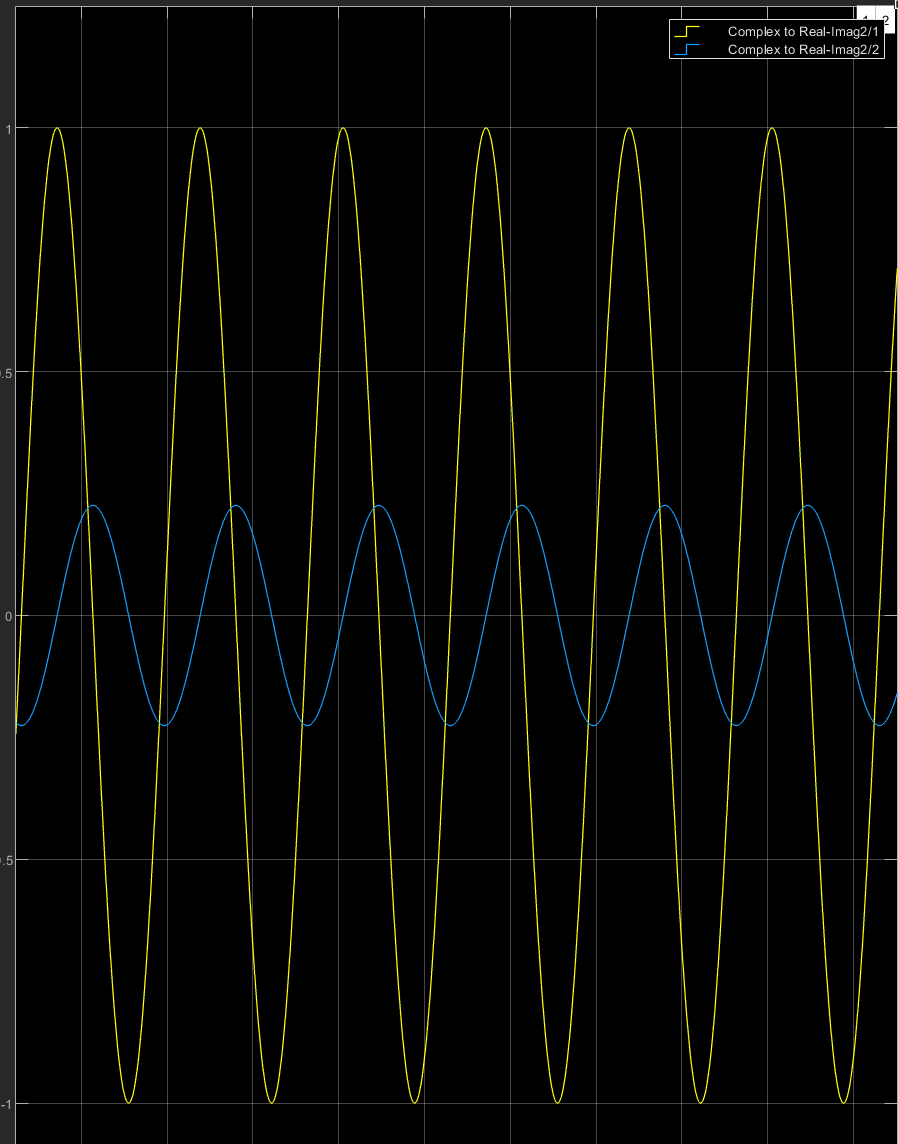
In Simulink, I have connected a sine wave to zero-order hold and zero-order hold to analytic signal block, as in the figure below. My purpose is to transform the real signal to the corresponding analytic signal by adding complex part, in order to be able to do some phase shifting operations. Zero-order hold block is to discretize the signal, as the analytic signal accepts only discrete signals. enter image description here Now, the problem is this: when I discretize the signal "more finely" by setting the sample time of zero-order hold to a smaller number (eg. 0.00003$0.00003$), imaginary part of the analytic signal output is reduced significantly, while the real part staying normally, as seen in the figure below. On the contrary, when the sample time is set to a greater number (eg. 0.0003$0.0003$) amplitudes of the real and the imaginary parts of the analytic signal output are the same, as expected.

enter image description here

According to the Matlab's documentation, analytic signal block's output is like this: $y=u+j H \{\ u \}\ $, where $H \{\ \}\ $ denotes the Hilbert transform and $j$ = $ \sqrt{-1}$. So, in the setup mentioned above it seems like when the continuous signal is sampled wıth a higher frequency, Hilbert transform reduces the amplitude.

Why would Hilbert transform reduce the amplitude, or is there a problem with my setup in Simulink?

In Simulink, I have connected a sine wave to zero-order hold and zero-order hold to analytic signal block, as in the figure below. My purpose is to transform the real signal to the corresponding analytic signal by adding complex part, in order to be able to do some phase shifting operations. Zero-order hold block is to discretize the signal, as the analytic signal accepts only discrete signals. enter image description here Now, the problem is this: when I discretize the signal "more finely" by setting the sample time of zero-order hold to a smaller number (eg. 0.00003), imaginary part of the analytic signal output is reduced significantly, while the real part staying normally, as seen in the figure below. On the contrary, when the sample time is set to a greater number (eg. 0.0003) amplitudes of the real and the imaginary parts of the analytic signal output are the same, as expected.

enter image description here

According to the Matlab's documentation, analytic signal block's output is like this: $y=u+j H \{\ u \}\ $, where $H \{\ \}\ $ denotes the Hilbert transform and $j$ = $ \sqrt{-1}$. So, in the setup mentioned above it seems like when the continuous signal is sampled wıth a higher frequency, Hilbert transform reduces the amplitude.

Why would Hilbert transform reduce the amplitude, or is there a problem with my setup in Simulink?

In Simulink, I have connected a sine wave to zero-order hold and zero-order hold to analytic signal block, as in the figure below. My purpose is to transform the real signal to the corresponding analytic signal by adding complex part, in order to be able to do some phase shifting operations. Zero-order hold block is to discretize the signal, as the analytic signal accepts only discrete signals. enter image description here Now, the problem is this: when I discretize the signal "more finely" by setting the sample time of zero-order hold to a smaller number (eg. $0.00003$), imaginary part of the analytic signal output is reduced significantly, while the real part staying normally, as seen in the figure below. On the contrary, when the sample time is set to a greater number (eg. $0.0003$) amplitudes of the real and the imaginary parts of the analytic signal output are the same, as expected.

enter image description here

According to the Matlab's documentation, analytic signal block's output is like this: $y=u+j H \{\ u \}\ $, where $H \{\ \}\ $ denotes the Hilbert transform and $j$ = $ \sqrt{-1}$. So, in the setup mentioned above it seems like when the continuous signal is sampled wıth a higher frequency, Hilbert transform reduces the amplitude.

Why would Hilbert transform reduce the amplitude, or is there a problem with my setup in Simulink?

In Simulink, I have connected a sine wave to zero-order hold and zero-order hold to analytic signal block, as in the figure below. My purpose is to transform the real signal to the corresponding analytic signal by adding complex part, in order to be able to do some phase shifting operations. Zero-order hold block is to discretize the signal, as the analytic signal accepts only discrete signals. enter image description here Now, the problem is this: when I discretize the signal "more finely" by setting the sample time of zero-order hold to a smaller number (eg. 0.00003), imaginary part of the analytic signal output is reduced significantly, while the real part staying normally, as seen in the figure below. On the contrary, when the sample time is set to a greater number (eg. 0.0003) amplitudes of the real and the imaginary parts of the analytic signal output are the same, as expected.

enter image description here

According to the Matlab's documentation, analytic signal block's output is like this: y=u+jH{u}$y=u+j H \{\ u \}\ $, H{} denotingwhere $H \{\ \}\ $ denotes the Hilbert transform and $j$ = $ \sqrt{-1}$. So, in the setup mentioned above it seems like when the continuous signal is sampled wıth a higher frequency, Hilbert transform reduces the amplitude.

Why would Hilbert transform reduce the amplitude, or is there a problem with my setup in Simulink?

In Simulink, I have connected a sine wave to zero-order hold and zero-order hold to analytic signal block, as in the figure below. My purpose is to transform the real signal to the corresponding analytic signal by adding complex part, in order to be able to do some phase shifting operations. Zero-order hold block is to discretize the signal, as the analytic signal accepts only discrete signals. enter image description here Now, the problem is this: when I discretize the signal "more finely" by setting the sample time of zero-order hold to a smaller number (eg. 0.00003), imaginary part of the analytic signal output is reduced significantly, while the real part staying normally, as seen in the figure below. On the contrary, when the sample time is set to a greater number (eg. 0.0003) amplitudes of the real and the imaginary parts of the analytic signal output are the same, as expected.

enter image description here

According to the Matlab's documentation, analytic signal block's output is like this: y=u+jH{u}, H{} denoting the Hilbert transform. So, in the setup mentioned above it seems like when the continuous signal is sampled wıth a higher frequency, Hilbert transform reduces the amplitude.

Why would Hilbert transform reduce the amplitude, or is there a problem with my setup in Simulink?

In Simulink, I have connected a sine wave to zero-order hold and zero-order hold to analytic signal block, as in the figure below. My purpose is to transform the real signal to the corresponding analytic signal by adding complex part, in order to be able to do some phase shifting operations. Zero-order hold block is to discretize the signal, as the analytic signal accepts only discrete signals. enter image description here Now, the problem is this: when I discretize the signal "more finely" by setting the sample time of zero-order hold to a smaller number (eg. 0.00003), imaginary part of the analytic signal output is reduced significantly, while the real part staying normally, as seen in the figure below. On the contrary, when the sample time is set to a greater number (eg. 0.0003) amplitudes of the real and the imaginary parts of the analytic signal output are the same, as expected.

enter image description here

According to the Matlab's documentation, analytic signal block's output is like this: $y=u+j H \{\ u \}\ $, where $H \{\ \}\ $ denotes the Hilbert transform and $j$ = $ \sqrt{-1}$. So, in the setup mentioned above it seems like when the continuous signal is sampled wıth a higher frequency, Hilbert transform reduces the amplitude.

Why would Hilbert transform reduce the amplitude, or is there a problem with my setup in Simulink?

Source Link
trxrg
  • 23
  • 3

Analytic Signal Block in Simulink Gives Reduced Amplitude for the Imaginary Part

In Simulink, I have connected a sine wave to zero-order hold and zero-order hold to analytic signal block, as in the figure below. My purpose is to transform the real signal to the corresponding analytic signal by adding complex part, in order to be able to do some phase shifting operations. Zero-order hold block is to discretize the signal, as the analytic signal accepts only discrete signals. enter image description here Now, the problem is this: when I discretize the signal "more finely" by setting the sample time of zero-order hold to a smaller number (eg. 0.00003), imaginary part of the analytic signal output is reduced significantly, while the real part staying normally, as seen in the figure below. On the contrary, when the sample time is set to a greater number (eg. 0.0003) amplitudes of the real and the imaginary parts of the analytic signal output are the same, as expected.

enter image description here

According to the Matlab's documentation, analytic signal block's output is like this: y=u+jH{u}, H{} denoting the Hilbert transform. So, in the setup mentioned above it seems like when the continuous signal is sampled wıth a higher frequency, Hilbert transform reduces the amplitude.

Why would Hilbert transform reduce the amplitude, or is there a problem with my setup in Simulink?