added 309 characters in body
Source Link
Dan Boschen
  • 55k
  • 2
  • 59
  • 143

Order refers to the order of the polynomial that is effectively used in the upsampling process. A zero-order hold will hold the previous value as a constant to insert all new interpolated samples, until the next sample, while a first-order interpolation will insert samples linearly between the existing samples, and so on.

Observe these two polynomial forms below using $m$ as the new higher rate samples and $n$ as the original lower rate samples, such that for $m = In$$N$ original samples with $n = 0 \ldots N-1$ there are $M$ higher rate samples with $M=In$ from $m = 0 \ldots M-1$, where $I$ is the upsampling factor:

Zero order hold:

$$y[m] = y[n-1]$$

First order hold:

$$y[m] = y[n-1] + \frac{m}{I}(y[n]-y[n-1]) $$$$y[m] = y[n-1] + \frac{m-In}{I}(y[n]-y[n-1]) $$

Often interpolation is done by upsampling by inserting zeros between the existing samples to have samples at the higher rate (and to be more complete in the mathematical forms above we would also operate on a zero-inserted signal at the higher rate to then show the two polynomial interpolations given with a consistent index of m), and this is followed by an interpolation filter which "grows" the zeros to the ideal (or close to ideal as limited by the filter design complexity) values for the interpolated signal.

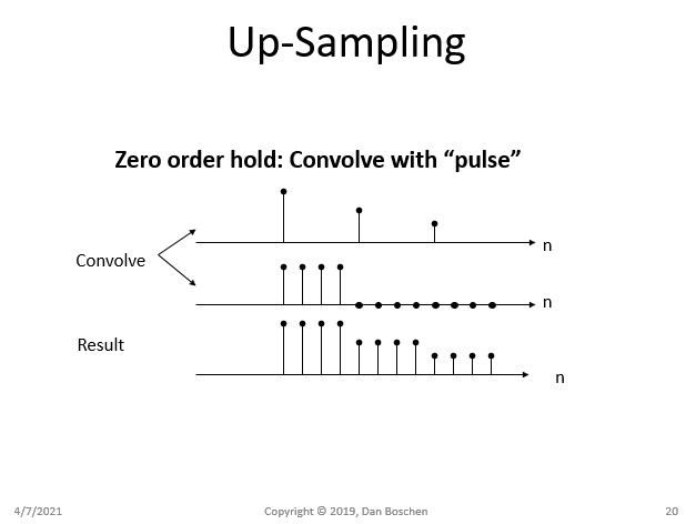
To see how this works, and the additional distortion that a zero-order hold approach would introduce (known as passband droop) please consider how a zero-order hold mathematically can be viewed as the convolution of our original signal with a (sampled) pulse as depicted in the figure below:

zero-order hold convolve with pulse

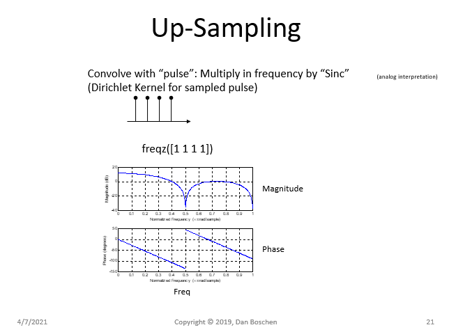
Convolution in the time domain is multiplication in the frequency domain. The Fourier Transform of a pulse is a Sinc function (and similarly the Discrete-Time Fourier Transform, DTFT, of a sampled pulse is the Dirichlet Kernel which is an aliased Sinc). This explains the "pass-band droop" distortion that a zero-hold upsampling would introduce as shown in the magnitude of the frequency response for the sampled pulse in the figure below (freqz is a Matlab/Octave/Python function which can produce the DTFT):

multiply with Sinc

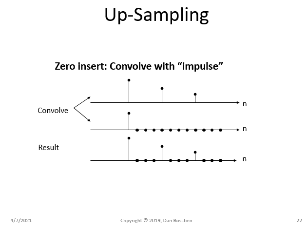
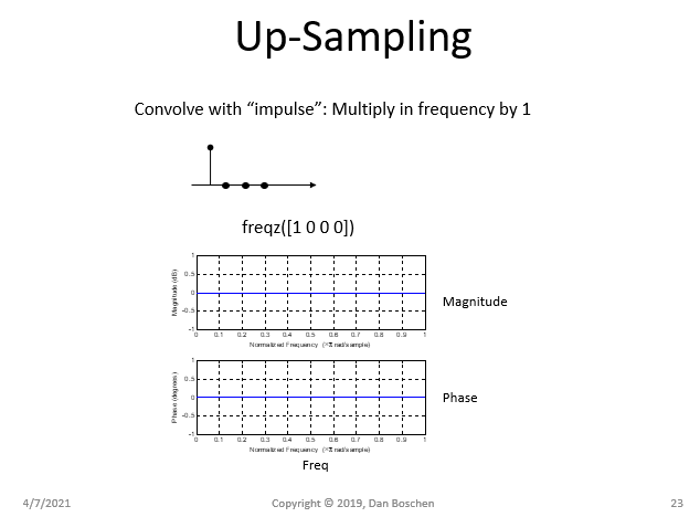
In contrast, a zero-insert approach would introduce no distortion within the passband of the signal (but replicates the spectrum in frequency which are removed with the interpolation filter):

up-sampling with zero insert

multiply by 1

As further detailed in other posts, the upsampling process will introduce spectral images that must be filtered out to complete the interpolation process. The ideal interpolation filter (ideal is not realizable but can be approached at the expense of filter complexity and can be designed to comply with any distortion requirements). For example, below shows the new images (in dashed lines) that would be created from an upsampling by 4 (introduce 3 zeros in between each sample), and the desired response of a multi-band interpolation FIR filter (IFIR) that ideally would pass the pass band with no distortion, and completely reject the images.

Interpolation FIR

Order refers to the order of the polynomial that is effectively used in the upsampling process. A zero-order hold will hold the previous value as a constant to insert all new interpolated samples, until the next sample, while a first-order interpolation will insert samples linearly between the existing samples, and so on.

Observe these two polynomial forms below using $m$ as the new higher rate samples and $n$ as the original lower rate samples, such that $m = In$ where $I$ is the upsampling factor:

Zero order hold:

$$y[m] = y[n-1]$$

First order hold:

$$y[m] = y[n-1] + \frac{m}{I}(y[n]-y[n-1]) $$

Often interpolation is done by upsampling by inserting zeros between the existing samples to have samples at the higher rate, and this is followed by an interpolation filter which "grows" the zeros to the ideal (or close to ideal as limited by the filter design complexity) values for the interpolated signal.

To see how this works, and the additional distortion that a zero-order hold approach would introduce (known as passband droop) please consider how a zero-order hold mathematically can be viewed as the convolution of our original signal with a (sampled) pulse as depicted in the figure below:

zero-order hold convolve with pulse

Convolution in the time domain is multiplication in the frequency domain. The Fourier Transform of a pulse is a Sinc function (and similarly the Discrete-Time Fourier Transform, DTFT, of a sampled pulse is the Dirichlet Kernel which is an aliased Sinc). This explains the "pass-band droop" distortion that a zero-hold upsampling would introduce as shown in the magnitude of the frequency response for the sampled pulse in the figure below (freqz is a Matlab/Octave/Python function which can produce the DTFT):

multiply with Sinc

In contrast, a zero-insert approach would introduce no distortion within the passband of the signal (but replicates the spectrum in frequency which are removed with the interpolation filter):

up-sampling with zero insert

multiply by 1

As further detailed in other posts, the upsampling process will introduce spectral images that must be filtered out to complete the interpolation process. The ideal interpolation filter (ideal is not realizable but can be approached at the expense of filter complexity and can be designed to comply with any distortion requirements). For example, below shows the new images (in dashed lines) that would be created from an upsampling by 4 (introduce 3 zeros in between each sample), and the desired response of a multi-band interpolation FIR filter (IFIR) that ideally would pass the pass band with no distortion, and completely reject the images.
Interpolation FIR

Order refers to the order of the polynomial that is effectively used in the upsampling process. A zero-order hold will hold the previous value as a constant to insert all new interpolated samples, until the next sample, while a first-order interpolation will insert samples linearly between the existing samples, and so on.

Observe these two polynomial forms below using $m$ as the new higher rate samples and $n$ as the original lower rate samples, such that for $N$ original samples with $n = 0 \ldots N-1$ there are $M$ higher rate samples with $M=In$ from $m = 0 \ldots M-1$, where $I$ is the upsampling factor:

Zero order hold:

$$y[m] = y[n-1]$$

First order hold:

$$y[m] = y[n-1] + \frac{m-In}{I}(y[n]-y[n-1]) $$

Often interpolation is done by upsampling by inserting zeros between the existing samples to have samples at the higher rate (and to be more complete in the mathematical forms above we would also operate on a zero-inserted signal at the higher rate to then show the two polynomial interpolations given with a consistent index of m), and this is followed by an interpolation filter which "grows" the zeros to the ideal (or close to ideal as limited by the filter design complexity) values for the interpolated signal.

To see how this works, and the additional distortion that a zero-order hold approach would introduce (known as passband droop) please consider how a zero-order hold mathematically can be viewed as the convolution of our original signal with a (sampled) pulse as depicted in the figure below:

zero-order hold convolve with pulse

Convolution in the time domain is multiplication in the frequency domain. The Fourier Transform of a pulse is a Sinc function (and similarly the Discrete-Time Fourier Transform, DTFT, of a sampled pulse is the Dirichlet Kernel which is an aliased Sinc). This explains the "pass-band droop" distortion that a zero-hold upsampling would introduce as shown in the magnitude of the frequency response for the sampled pulse in the figure below (freqz is a Matlab/Octave/Python function which can produce the DTFT):

multiply with Sinc

In contrast, a zero-insert approach would introduce no distortion within the passband of the signal (but replicates the spectrum in frequency which are removed with the interpolation filter):

up-sampling with zero insert

multiply by 1

As further detailed in other posts, the upsampling process will introduce spectral images that must be filtered out to complete the interpolation process. The ideal interpolation filter (ideal is not realizable but can be approached at the expense of filter complexity and can be designed to comply with any distortion requirements). For example, below shows the new images (in dashed lines) that would be created from an upsampling by 4 (introduce 3 zeros in between each sample), and the desired response of a multi-band interpolation FIR filter (IFIR) that ideally would pass the pass band with no distortion, and completely reject the images.
Interpolation FIR

added 309 characters in body
Source Link
Dan Boschen
  • 55k
  • 2
  • 59
  • 143

Order refers to the order of the polynomial that is effectively used in the upsampling process. A zero-order hold will hold the previous value as a constant to insert all new interpolated samples, until the next sample, while a first-order interpolation will insert samples linearly between the existing samples, and so on.

Observe these two polynomial forms below using $m$ as the new higher rate samples and $n$ as the original lower rate samples, such that $m = In$ where $I$ is the upsampling factor:

Zero order hold:

$$y[m] = y[x[n-1]]$$$$y[m] = y[n-1]$$

First order hold:

$$y[m] = x[n-1] + x[m] \frac{y[n]-y[n-1]}{x[n]-x[n-1]} $$$$y[m] = y[n-1] + \frac{m}{I}(y[n]-y[n-1]) $$

Often interpolation is done by upsampling by inserting zeros between the existing samples to have samples at the higher rate, and this is followed by an interpolation filter which "grows" the zeros to the ideal (or close to ideal as limited by the filter design complexity) values for the interpolated signal.

To see how this works, and the additional distortion that a zero-order hold approach would introduce (known as passband droop) please consider how a zero-order hold mathematically can be viewed as the convolution of our original signal with a (sampled) pulse as depicted in the figure below:

zero-order hold convolve with pulse

Convolution in the time domain is multiplication in the frequency domain. The Fourier Transform of a pulse is a Sinc function (and similarly the Discrete-Time Fourier Transform, DTFT, of a sampled pulse is the Dirichlet Kernel which is an aliased Sinc). This explains the "pass-band droop" distortion that a zero-hold upsampling would introduce as shown in the magnitude of the frequency response for the sampled pulse in the figure below (freqz is a Matlab/Octave/Python function which can produce the DTFT):

multiply with Sinc

In contrast, a zero-insert approach would introduce no distortion within the passband of the signal (but replicates the spectrum in frequency which are removed with the interpolation filter):

up-sampling with zero insert

multiply by 1

As further detailed in other posts, the upsampling process will introduce spectral images that must be filtered out to complete the interpolation process. The ideal interpolation filter (ideal is not realizable but can be approached at the expense of filter complexity and can be designed to comply with any distortion requirements). For example, below shows the new images (in dashed lines) that would be created from an upsampling by 4 (introduce 3 zeros in between each sample), and the desired response of a multi-band interpolation FIR filter (IFIR) that ideally would pass the pass band with no distortion, and completely reject the images.
Interpolation FIR

Order refers to the order of the polynomial that is effectively used in the upsampling process. A zero-order hold will hold the previous value as a constant to insert all new interpolated samples, until the next sample, while a first-order interpolation will insert samples linearly between the existing samples, and so on.

Observe these two polynomial forms below using $m$ as the new higher rate samples and $n$ as the original lower rate samples, such that $m = In$ where $I$ is the upsampling factor:

Zero order hold:

$$y[m] = y[x[n-1]]$$

First order hold:

$$y[m] = x[n-1] + x[m] \frac{y[n]-y[n-1]}{x[n]-x[n-1]} $$

Often interpolation is done by upsampling by inserting zeros between the existing samples to have samples at the higher rate, and this is followed by an interpolation filter which "grows" the zeros to the ideal (or close to ideal as limited by the filter design complexity) values for the interpolated signal.

To see how this works, and the additional distortion that a zero-order hold approach would introduce (known as passband droop) please consider how a zero-order hold mathematically can be viewed as the convolution of our original signal with a (sampled) pulse as depicted in the figure below:

zero-order hold convolve with pulse

Convolution in the time domain is multiplication in the frequency domain. The Fourier Transform of a pulse is a Sinc function (and similarly the Discrete-Time Fourier Transform, DTFT, of a sampled pulse is the Dirichlet Kernel which is an aliased Sinc). This explains the "pass-band droop" distortion that a zero-hold upsampling would introduce as shown in the magnitude of the frequency response for the sampled pulse in the figure below (freqz is a Matlab/Octave/Python function which can produce the DTFT):

multiply with Sinc

In contrast, a zero-insert approach would introduce no distortion within the passband of the signal (but replicates the spectrum in frequency which are removed with the interpolation filter):

up-sampling with zero insert

multiply by 1

As further detailed in other posts, the upsampling process will introduce spectral images that must be filtered out to complete the interpolation process. The ideal interpolation filter (ideal is not realizable but can be approached at the expense of filter complexity and can be designed to comply with any distortion requirements). For example, below shows the new images (in dashed lines) that would be created from an upsampling by 4 (introduce 3 zeros in between each sample), and the desired response of a multi-band interpolation FIR filter (IFIR) that ideally would pass the pass band with no distortion, and completely reject the images.
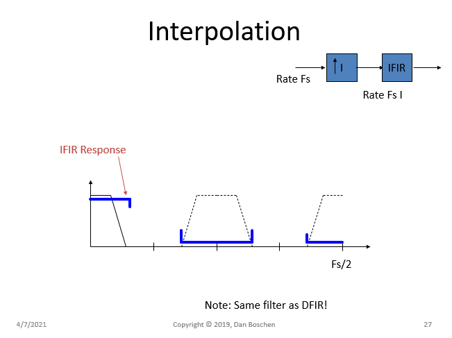
Interpolation FIR

Order refers to the order of the polynomial that is effectively used in the upsampling process. A zero-order hold will hold the previous value as a constant to insert all new interpolated samples, until the next sample, while a first-order interpolation will insert samples linearly between the existing samples, and so on.

Observe these two polynomial forms below using $m$ as the new higher rate samples and $n$ as the original lower rate samples, such that $m = In$ where $I$ is the upsampling factor:

Zero order hold:

$$y[m] = y[n-1]$$

First order hold:

$$y[m] = y[n-1] + \frac{m}{I}(y[n]-y[n-1]) $$

Often interpolation is done by upsampling by inserting zeros between the existing samples to have samples at the higher rate, and this is followed by an interpolation filter which "grows" the zeros to the ideal (or close to ideal as limited by the filter design complexity) values for the interpolated signal.

To see how this works, and the additional distortion that a zero-order hold approach would introduce (known as passband droop) please consider how a zero-order hold mathematically can be viewed as the convolution of our original signal with a (sampled) pulse as depicted in the figure below:

zero-order hold convolve with pulse

Convolution in the time domain is multiplication in the frequency domain. The Fourier Transform of a pulse is a Sinc function (and similarly the Discrete-Time Fourier Transform, DTFT, of a sampled pulse is the Dirichlet Kernel which is an aliased Sinc). This explains the "pass-band droop" distortion that a zero-hold upsampling would introduce as shown in the magnitude of the frequency response for the sampled pulse in the figure below (freqz is a Matlab/Octave/Python function which can produce the DTFT):

multiply with Sinc

In contrast, a zero-insert approach would introduce no distortion within the passband of the signal (but replicates the spectrum in frequency which are removed with the interpolation filter):

up-sampling with zero insert

multiply by 1

As further detailed in other posts, the upsampling process will introduce spectral images that must be filtered out to complete the interpolation process. The ideal interpolation filter (ideal is not realizable but can be approached at the expense of filter complexity and can be designed to comply with any distortion requirements). For example, below shows the new images (in dashed lines) that would be created from an upsampling by 4 (introduce 3 zeros in between each sample), and the desired response of a multi-band interpolation FIR filter (IFIR) that ideally would pass the pass band with no distortion, and completely reject the images.

Interpolation FIR

added 309 characters in body
Source Link
Dan Boschen
  • 55k
  • 2
  • 59
  • 143

Order refers to the order of the polynomial that is effectively used in the upsampling process. A zero-order hold will hold the previous value as a constant to insert all new interpolated samples, until the next sample, while a first-order interpolation will insert samples linearly between the existing samples, and so on.

Observe these two polynomial forms below using $m$ as the new higher rate samples and $n$ as the original lower rate samples, such that $m = In$ where $I$ is the upsampling factor:

Zero order hold:

$$y[m] = y[x[n-1]]$$

First order hold:

$$y[m] = x[n-1] + x[m] \frac{y[n]-y[n-1]}{x[n]-x[n-1]} $$

Often interpolation is done by upsampling by inserting zeros between the existing samples to have samples at the higher rate, and this is followed by an interpolation filter which "grows" the zeros to the ideal (or close to ideal as limited by the filter design complexity) values for the interpolated signal.

To see how this works, and the additional distortion that a zero-order hold approach would introduce (known as passband droop) please consider how a zero-order hold mathematically can be viewed as the convolution of our original signal with a (sampled) pulse as depicted in the figure below:

zero-order hold convolve with pulse

Convolution in the time domain is multiplication in the frequency domain. The Fourier Transform of a pulse is a Sinc function (and similarly the Discrete-Time Fourier Transform, DTFT, of a sampled pulse is the Dirichlet Kernel which is an aliased Sinc). This explains the "pass-band droop" distortion that a zero-hold upsampling would introduce as shown in the magnitude of the frequency response for the sampled pulse in the figure below (freqz is a Matlab/Octave/Python function which can produce the DTFT):

multiply with Sinc

In contrast, a zero-insert approach would introduce no distortion within the passband of the signal (but replicates the spectrum in frequency which are removed with the interpolation filter):

up-sampling with zero insert

multiply by 1

As further detailed in other posts, the upsampling process will introduce spectral images that must be filtered out to complete the interpolation process. The ideal interpolation filter (ideal is not realizable but can be approached at the expense of filter complexity and can be designed to comply with any distortion requirements). For example, below shows the new images (in dashed lines) that would be created from an upsampling by 4 (introduce 3 zeros in between each sample), and the desired response of a multi-band interpolation FIR filter (IFIR) that ideally would pass the pass band with no distortion, and completely reject the images.

Interpolation FIR

Order refers to the order of the polynomial that is effectively used in the upsampling process. A zero-order hold will hold the previous value as a constant to insert all new interpolated samples, until the next sample, while a first-order interpolation will insert samples linearly between the existing samples, and so on.

Observe these two polynomial forms below using $m$ as the new higher rate samples and $n$ as the original lower rate samples, such that $m = In$ where $I$ is the upsampling factor:

Zero order hold:

$$y[m] = y[x[n-1]]$$

First order hold:

$$y[m] = x[n-1] + x[m] \frac{y[n]-y[n-1]}{x[n]-x[n-1]} $$

Often interpolation is done by upsampling by inserting zeros between the existing samples to have samples at the higher rate, and this is followed by an interpolation filter which "grows" the zeros to the ideal (or close to ideal as limited by the filter design complexity) values for the interpolated signal.

To see how this works, and the additional distortion that a zero-order hold approach would introduce (known as passband droop) please consider how a zero-order hold mathematically can be viewed as the convolution of our original signal with a (sampled) pulse as depicted in the figure below:

zero-order hold convolve with pulse

Convolution in the time domain is multiplication in the frequency domain. The Fourier Transform of a pulse is a Sinc function (and similarly the Discrete-Time Fourier Transform, DTFT, of a sampled pulse is the Dirichlet Kernel which is an aliased Sinc). This explains the "pass-band droop" distortion that a zero-hold upsampling would introduce as shown in the magnitude of the frequency response for the sampled pulse in the figure below (freqz is a Matlab/Octave/Python function which can produce the DTFT):

multiply with Sinc

In contrast, a zero-insert approach would introduce no distortion within the passband of the signal (but replicates the spectrum in frequency which are removed with the interpolation filter):

up-sampling with zero insert

multiply by 1

As further detailed in other posts, the upsampling process will introduce spectral images that must be filtered out to complete the interpolation process. The ideal interpolation filter (ideal is not realizable but can be approached at the expense of filter complexity and can be designed to comply with any distortion requirements). For example, below shows the new images (in dashed lines) that would be created from an upsampling by 4 (introduce 3 zeros in between each sample), and the desired response of a multi-band interpolation FIR filter (IFIR) that ideally would pass the pass band with no distortion, and completely reject the images.

Interpolation FIR

added 2 characters in body
Source Link
Dan Boschen
  • 55k
  • 2
  • 59
  • 143
Loading
added 352 characters in body
Source Link
Dan Boschen
  • 55k
  • 2
  • 59
  • 143
Loading
Source Link
Dan Boschen
  • 55k
  • 2
  • 59
  • 143
Loading