One problem with your design is that the quantized numerator coefficients don't add up to zero anymore, so you lose the desired notch at DC. That can be done differently, because even with quantized coefficients you can have a (double) zero at DC. Just make sure that $b[0]=b[2]$ and $b[1]=-2b[0]$.
The real problem is with the denominator polynomial. It is well known that the available pole locations resulting from quantizing the polynomial coefficients are very sparse at low frequencies.
Note that the maximum magnitude of the ideal coefficients is close to $2$, so in order to quantize the coefficients to $16$ bits, you need to scale by $2^{14}$ instead of by $2^{15}$. This will result in the correct value range of the quantized integer coefficients:
bb = round( b * 2^14 ) * 2^(-14);
aa = round( a * 2^14 ) * 2^(-14);
The resulting quantized numerator coefficients guarantee a double zero at DC. However, the quantized denominator coefficients result in two real-valued poles, one of which is on the unit circle. I.e., there is a pole-zero cancellation and you end up with a first-order filter.
So one of the options you have is to use a first-order filter instead of a second-order filter. The numerator coefficients are trivial in this case:
b1 = [1,-1];
The denominator coefficient can be chosen experimentally using some negative value close to (but smaller in magnitude than) $-1$. Of course that value must be representable using $16$ bits:
a1 = [1, round( -r * 2^(15) ) * 2^(-15)];
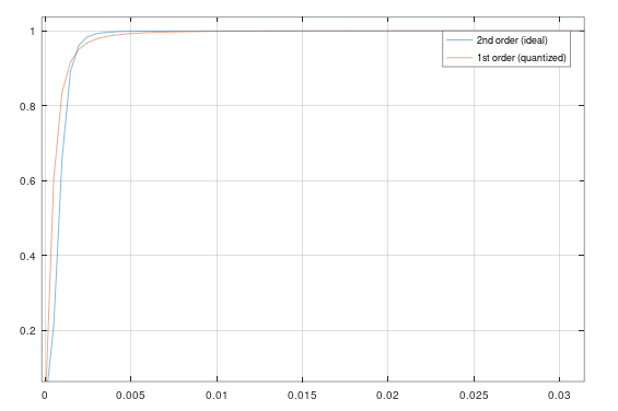
The plot below shows the frequency response of the ideal second-order filter (blue) and of the quantized first-order filter with $r=0.998$. You have to judge for yourself if the deviation from the ideal response is tolerable for you application or not.
Another solution is to use a different filter structure which is more robust to coefficient quantization (at least at low frequencies). Such a structure is the coupled-form structure, which is described in most textbooks on DSP (e.g., in Oppenheim's Discrete-Time Signal Processing).

