added combined plot
Source Link
Jason R
  • 24.8k
  • 2
  • 70
  • 74

The first equation you give is the difference equation for a lowpass FIR filter, or a linear filter with an impulse response that is finite in duration. I'll write it a bit differently (so that it is expressly discrete in time and causal):

$$ f_s[n] = 0.1 f[n-2] + 0.8 f[n-1] + 0.1 f[n] $$

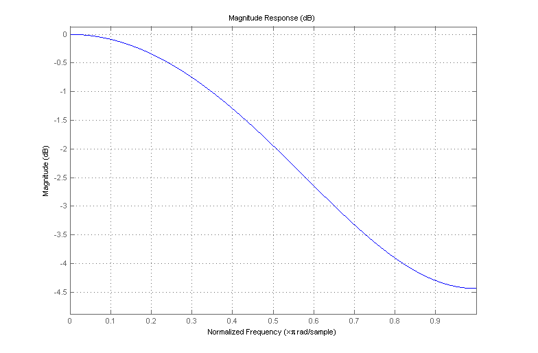
$f_s[n]$ is the smoothed version of the discrete-time input sequence $f[n]$, generated by passing $f[n]$ through an FIR filter with the coefficients $[0.1, 0.8, 0.1]$. The frequency response of this filter is as follows:
enter image description here

As it turns out, it's not a very good lowpass filter. As the name implies, a lowpass filter should pass low-frequency content while removing higher frequencies. This provides the "smoothing" action that you're looking for, as "jagged", non-smooth features are associated with high frequencies since they change rapidly with time.

Your second equation is an example of a lowpass IIR filter, a linear filter whose impulse response is infinite in duration. The filter's difference equation is:

$$ y[n] = \alpha y[n-1] + (1-\alpha) x[n] $$

where $x[n]$ is the filter input and $y[n]$ is the filter output. This type of filter is often used as a low-complexity lowpass filter and is often called a leaky integrator. It is favored because of its simple implementation, low computational complexity, and its tunability: its cutoff frequency depends upon the value of $\alpha$. $\alpha$ can take on values on the interval $[0,1)$. $\alpha = 0$ yields no filtering at all (the output is equal to the input); as $\alpha$ increases, the cutoff frequency of the filter decreases. You can think of $\alpha = 1$ as a boundary case where the cutoff frequency is infinitely low (the filter output is zero for all time).

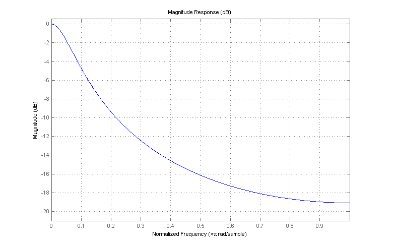
As an example, if $\alpha = 0.8$, the frequency response of the filter is as follows:
enter image description here

which is a better filter than your FIR example; it yields much better attenuation of frequencies toward the upper end of the band. Even though it might not be obvious by looking at the difference equation (because of the feedback from the filter output back to its input), it effectively performs smoothing on the input due to its lowpass nature. I'm not sure if this description will be particularly meaningful to you for your application, but these are pretty fundamental signal processing concepts; some study of introductory DSP texts could help fill in the gaps.

Edit: By request, here's a plot that shows both responses on the same axes, illustrating the relatively poor attenuation provided by the FIR example filter:

enter image description here

The first equation you give is the difference equation for a lowpass FIR filter, or a linear filter with an impulse response that is finite in duration. I'll write it a bit differently (so that it is expressly discrete in time and causal):

$$ f_s[n] = 0.1 f[n-2] + 0.8 f[n-1] + 0.1 f[n] $$

$f_s[n]$ is the smoothed version of the discrete-time input sequence $f[n]$, generated by passing $f[n]$ through an FIR filter with the coefficients $[0.1, 0.8, 0.1]$. The frequency response of this filter is as follows:

enter image description here

As it turns out, it's not a very good lowpass filter. As the name implies, a lowpass filter should pass low-frequency content while removing higher frequencies. This provides the "smoothing" action that you're looking for, as "jagged", non-smooth features are associated with high frequencies since they change rapidly with time.

Your second equation is an example of a lowpass IIR filter, a linear filter whose impulse response is infinite in duration. The filter's difference equation is:

$$ y[n] = \alpha y[n-1] + (1-\alpha) x[n] $$

where $x[n]$ is the filter input and $y[n]$ is the filter output. This type of filter is often used as a low-complexity lowpass filter and is often called a leaky integrator. It is favored because of its simple implementation, low computational complexity, and its tunability: its cutoff frequency depends upon the value of $\alpha$. $\alpha$ can take on values on the interval $[0,1)$. $\alpha = 0$ yields no filtering at all (the output is equal to the input); as $\alpha$ increases, the cutoff frequency of the filter decreases. You can think of $\alpha = 1$ as a boundary case where the cutoff frequency is infinitely low (the filter output is zero for all time).

As an example, if $\alpha = 0.8$, the frequency response of the filter is as follows:

enter image description here

which is a better filter than your FIR example; it yields much better attenuation of frequencies toward the upper end of the band. Even though it might not be obvious by looking at the difference equation (because of the feedback from the filter output back to its input), it effectively performs smoothing on the input due to its lowpass nature. I'm not sure if this description will be particularly meaningful to you for your application, but these are pretty fundamental signal processing concepts; some study of introductory DSP texts could help fill in the gaps.

Edit: By request, here's a plot that shows both responses on the same axes, illustrating the relatively poor attenuation provided by the FIR example filter:

enter image description here

Source Link
Jason R
  • 24.8k
  • 2
  • 70
  • 74

The first equation you give is the difference equation for a lowpass FIR filter, or a linear filter with an impulse response that is finite in duration. I'll write it a bit differently (so that it is expressly discrete in time and causal):

$$ f_s[n] = 0.1 f[n-2] + 0.8 f[n-1] + 0.1 f[n] $$

$f_s[n]$ is the smoothed version of the discrete-time input sequence $f[n]$, generated by passing $f[n]$ through an FIR filter with the coefficients $[0.1, 0.8, 0.1]$. The frequency response of this filter is as follows:

enter image description here

As it turns out, it's not a very good lowpass filter. As the name implies, a lowpass filter should pass low-frequency content while removing higher frequencies. This provides the "smoothing" action that you're looking for, as "jagged", non-smooth features are associated with high frequencies since they change rapidly with time.

Your second equation is an example of a lowpass IIR filter, a linear filter whose impulse response is infinite in duration. The filter's difference equation is:

$$ y[n] = \alpha y[n-1] + (1-\alpha) x[n] $$

where $x[n]$ is the filter input and $y[n]$ is the filter output. This type of filter is often used as a low-complexity lowpass filter and is often called a leaky integrator. It is favored because of its simple implementation, low computational complexity, and its tunability: its cutoff frequency depends upon the value of $\alpha$. $\alpha$ can take on values on the interval $[0,1)$. $\alpha = 0$ yields no filtering at all (the output is equal to the input); as $\alpha$ increases, the cutoff frequency of the filter decreases. You can think of $\alpha = 1$ as a boundary case where the cutoff frequency is infinitely low (the filter output is zero for all time).

As an example, if $\alpha = 0.8$, the frequency response of the filter is as follows:

enter image description here

which is a better filter than your FIR example; it yields much better attenuation of frequencies toward the upper end of the band. Even though it might not be obvious by looking at the difference equation (because of the feedback from the filter output back to its input), it effectively performs smoothing on the input due to its lowpass nature. I'm not sure if this description will be particularly meaningful to you for your application, but these are pretty fundamental signal processing concepts; some study of introductory DSP texts could help fill in the gaps.