4
$\begingroup$

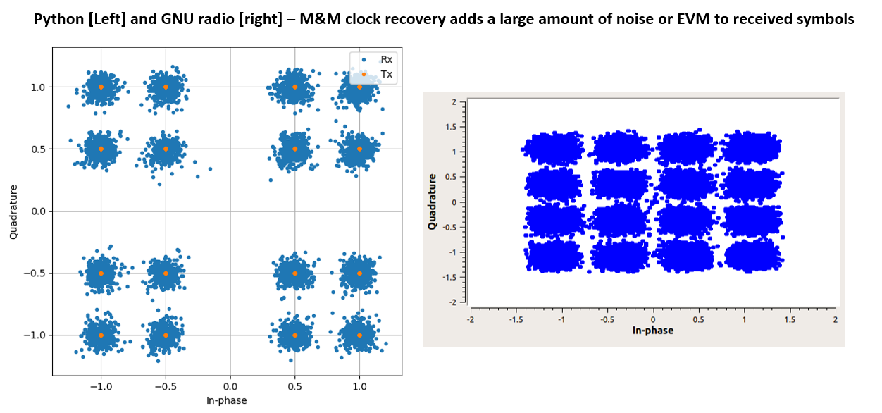
The implementation of the Mueller and Muller clock recovery that I am seeing adds a large amount of 'noise' or degradation to the Error Vector Magnitude (EVM) to the symbols on the constellation. This is done independently in GNU Radio and a manual script in Python - giving similar results. Is this normal?

I understand that I need to adjust the parameters in this algorithm but I cant get anywhere near an optimisation that is adequate, its too noisy.

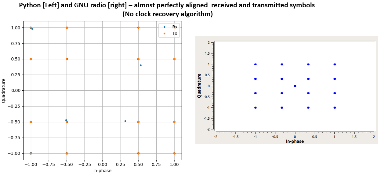
In both implementations GNU radio and python , the only impairment to the original data signal is the performance of the RRC pulse shaping filters. You can see that's its an almost perfect received constellation with an EVM < -60 dB using a filter taps of 300 and roll off factor of 0.35. See below image.

enter image description here

However, once I add the M&M algorithm I have no luck getting anywhere close to this and it generates a lot of noise. See below image.

enter image description here

It somewhat makes it difficult to assess the true extent of impairments I may later add in the model, like AWGN. Because if I add AWGN to this then the EVM or SNR just gets worse when the M&M is being used.

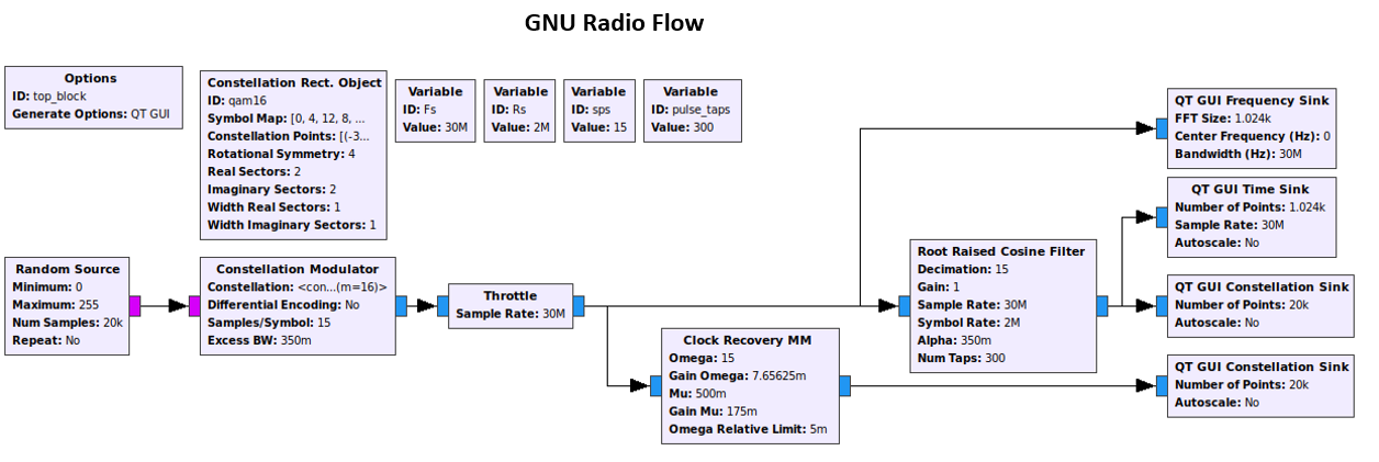
Here is the GNU radio flow.

EDIT Note that in my python code the Rx RRC filter is performed before the M&M, but in GNU radio I do it before an RRC because having an RRC before the MM block doesn't work give any result in the flow below.

enter image description here

Below is the M&M python algorithm, its from pySDR.com

samples = input_signal
interp = 16
samples_interpolated = signal.resample_poly(samples,interp,1)
mu = 2 #2 # initial estimate of phase of sample
out = np.zeros(len(samples) + 10, dtype=np.complex)
out_rail = np.zeros(len(samples) + 10, dtype=np.complex) # stores values, each iteration we need the previous 2 values plus current value
i_in = 0 # input samples index
i_out = 2 # output index (let first two outputs be 0)
while i_out < len(samples) and i_in < len(samples):
    out[i_out] = samples_interpolated[i_in*interp + int(mu*interp)] # grab what we think is the "best" sample
    out_rail[i_out] = int(np.real(out[i_out]) > 0) + 1j*int(np.imag(out[i_out]) > 0)
    z = (out_rail[i_out] - out_rail[i_out-2]) * np.conj(out[i_out-1])
    zz = (out[i_out] - out[i_out-2]) * np.conj(out_rail[i_out-1])
    mm_val = np.real(zz - z)
    mu += sps + 0.3*mm_val
    i_in += int(np.floor(mu)) # round down to nearest int since we are using it as an index
    mu = mu - np.floor(mu) # remove the integer part of mu
    i_out += 1 # increment output index
out = out[2:i_out-1] # remove the first two, and anything after i_out (that was never filled out)
$\endgroup$
4
  • $\begingroup$ The distortion is sometimes referred to as “self noise”. The M&M tend to have issues when the number of samples per symbol is greater than 8. Have you tried other algorithms like the pfb in GNU Radio? $\endgroup$ Commented May 16, 2021 at 12:01
  • $\begingroup$ @MosesBrowneMwakyanjala I have tried lowering sps but to no avail in my python script and GNU radio. Do you have any recommendations of python code for timing recovery like that pfb in GNU radio tutorial? $\endgroup$ Commented May 16, 2021 at 18:49
  • $\begingroup$ I don't know of any python implementation for the PFB. The C++ code is however available on the GNU Radio source tree. In the meantime, you could try different TEDs by changing the mm_val to say Early-Late, Maximum-likelihood (difference), Gardner, Zero-Crossing etc. You can find the formulas for these TEDs online. $\endgroup$ Commented May 17, 2021 at 16:32
  • $\begingroup$ Hello, your 16 QAM constellation in Python (left) is not proper btw. The spacing between the constellation points is not equal. $\endgroup$ Commented Oct 27, 2021 at 21:43

1 Answer 1

4
$\begingroup$

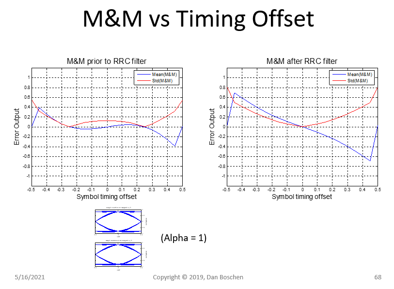
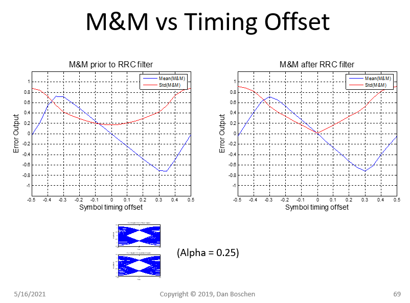
Unlike the Gardner Loop, the M&M synchronizer should be performed after the RRC filter in the receiver for best performance. With cases of high RRC alpha, the M&M won't work as expected without the complete Raised-Cosine filtering (RRC in transmitter followed by RRC in receiver) as the slope of the error term will reverse, with high self-noise, as I demonstrate in this plot below:

M&M discriminator

The blue line is the discriminator output showing average error versus offset, and the red line is the standard deviation of that error showing the self-noise. In the first case the slope of error output versus offset actually inverts in proximity of the lock point (so it would work, barely, if the feedback is inverted but with very high self-noise and low slope so very low timing SNR otherwise it would lock interestingly at 1/4 sample offset).

Specific to the OP's case, below is the same chart with a lower (and typical) RRC alpha where the discriminator curve is quite similar but the self-noise is much higher at the lock condition if the M&M is used prior to the second RRC filter.

M&M low alpha

Both the Gardner Loop and M&M will have self noise, but the self noise is typically averaged out in the recovery loop to be well below the receiver noise floor once the accumulated time sample location is determined for each new sample.

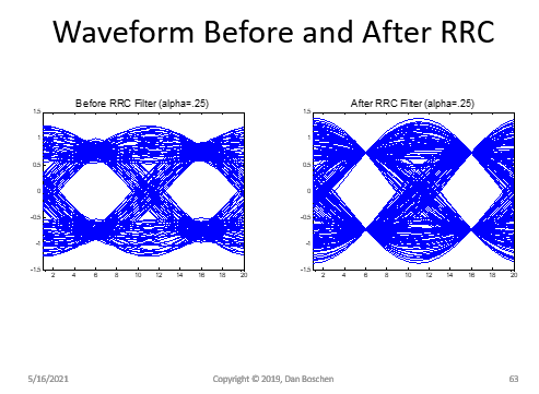
Why the difference between Gardner and M&M? It is interesting that the Gardner performs better using the samples prior to the second RRC filter while the M&M synchronizer is better after. This is because the M&M synchronizer operates on one sample per symbol using sample locations at the decision locations and thus depends on the slope of the waveform in vicinity of these locations to determine timing error. The Gardner operates using 2 samples per symbol and operates by approximating the slope at the zero crossings, which have less timing jitter before the second RRC filter as we see in the eye diagrams below (notice the wider range of zero-crossing transition times in the waveform after the second RRC filter):

waveform before and after RRC

Generally for timing detection our best estimates should be obtained from the zero crossings where the slope and therefore sensitivity to timing error would be highest. This is true on average and is one of the reasons the Gardner Loop has better SNR performance in low SNR conditions (and M&M has better performance in high SNR conditions since it uses decisions in its computation, which eliminate noise if the decisions are correct). However, the competing requirement of having no inter-symbol interference at the data decision location results in increased zero-crossing jitter at the waveform locations of interest for timing detection. One solution to this if self-noise was an issue (it typically isn't as the timing loop bandwidth is so much smaller as to average it out) is the use of pre-filters which can equalize the ISI at the zero crossing locations for timing detection, on a separate data-path from the data which has zero ISI at the symbol detection locations as desired for best data-recovery performance.

$\endgroup$
7
  • $\begingroup$ in my python script the Rx RRC is done before the M&M. But okay I will look into that for GNU radio because if I plug the MM block to the output of the Rx RRC in the flow posted above then it doesn't work at all. $\endgroup$ Commented May 16, 2021 at 13:16
  • $\begingroup$ @Villere_DSP I don’t see in your Python script where you have any control of your loop BW— if the timing loop BW is too wide then all the self noise will pass through while what you want is the averaged result. Perhaps try lowering the constant 0.3 as that appears to be your loop gain. $\endgroup$ Commented May 16, 2021 at 14:46
  • $\begingroup$ Its code from pysdr.com thats advised on GNUradio so I didnt write it myself. The 0.3 if too small causes very large EVM to total loss, I havent found a value thats suitable with many many many tries of it. Interesting, as the author of the site shows it works well with BPSK but I cant get it working with anything other than BPSK. Do you have any recommendations of python code or libraries that have timing recovery algorithms? $\endgroup$ Commented May 16, 2021 at 18:48
  • $\begingroup$ I wasn’t thinking too small but too large- to reduce the loop bandwidth you would make it smaller. Oh, if the author shows it working for BPSK it may not be the full complex version for QPSK. Your quick work-around is to use it on I or Q only which would be BPSK signals. No I don’t, as the algorithm is pretty straightforward to just implement directly. $\endgroup$ Commented May 16, 2021 at 18:59
  • $\begingroup$ (Meaning use of for I demod and another for Q demod; not ideal but can be implemented with what you have). If you resort to implementing it yourself, I suggest the Gardner timing detector as an algorithm of choice since it can operate under significantly higher carrier offsets than the M&M $\endgroup$ Commented May 16, 2021 at 19:52

Your Answer

By clicking “Post Your Answer”, you agree to our terms of service and acknowledge you have read our privacy policy.

Not the answer you're looking for? Browse other questions tagged or ask your own question.